- 快召唤伙伴们来围观吧
- 微博 QQ QQ空间 贴吧
- 文档嵌入链接
- 复制
- 微信扫一扫分享
- 已成功复制到剪贴板
低功耗集成电路体系结构、算法和系统
展开查看详情
1 .Optimizing Power @ Design Time Architectures, Algorithms and Systems
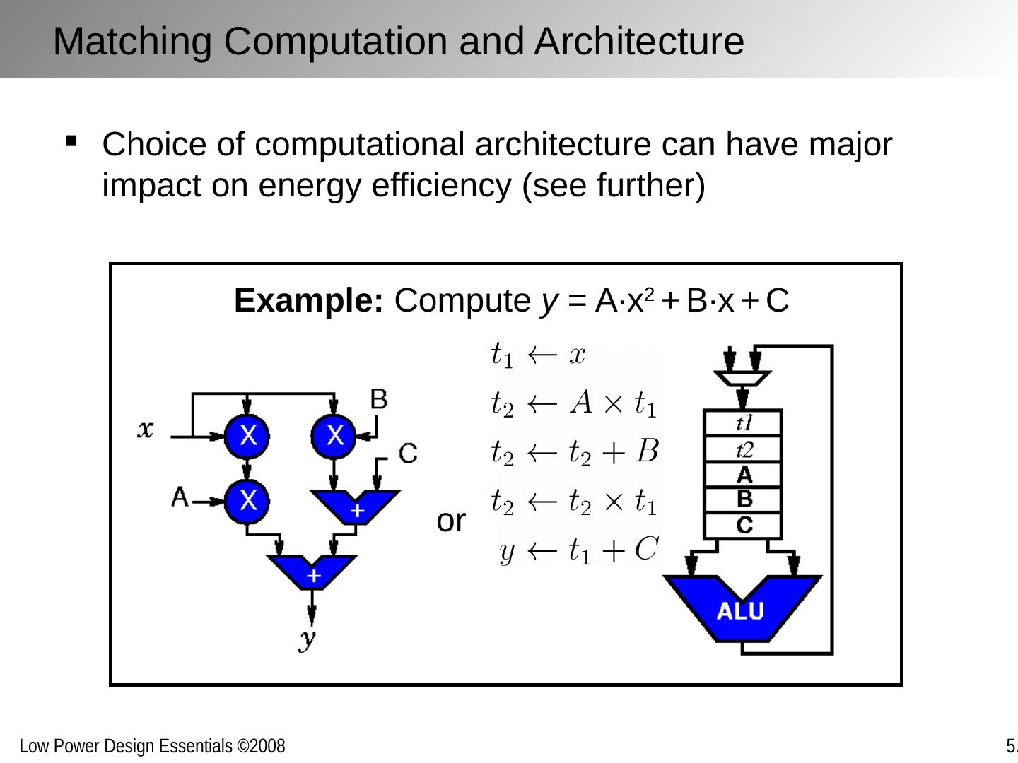
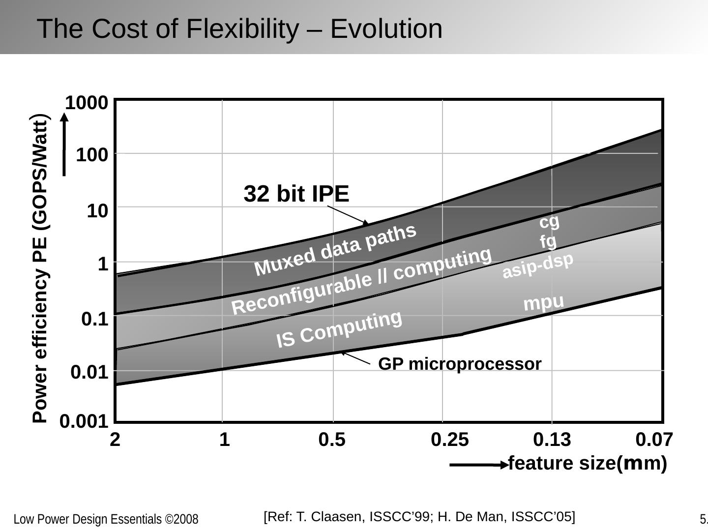
2 .Chapter Outline The architecture/system trade-off space Concurrency improves energy-efficiency Exploring alternative topologies Removing inefficiency The cost of flexibility
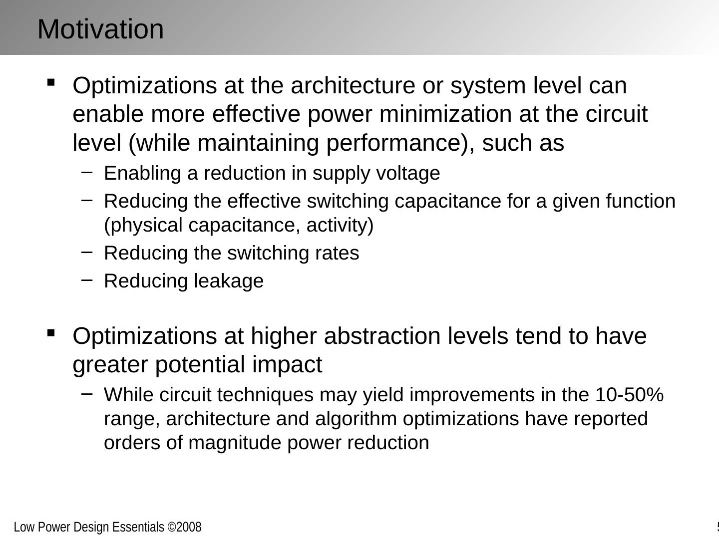
3 .Motivation Optimizations at the architecture or system level can enable more effective power minimization at the circuit level (while maintaining performance), such as Enabling a reduction in supply voltage Reducing the effective switching capacitance for a given function (physical capacitance, activity) Reducing the switching rates Reducing leakage Optimizations at higher abstraction levels tend to have greater potential impact While circuit techniques may yield improvements in the 10-50% range, architecture and algorithm optimizations have reported orders of magnitude power reduction
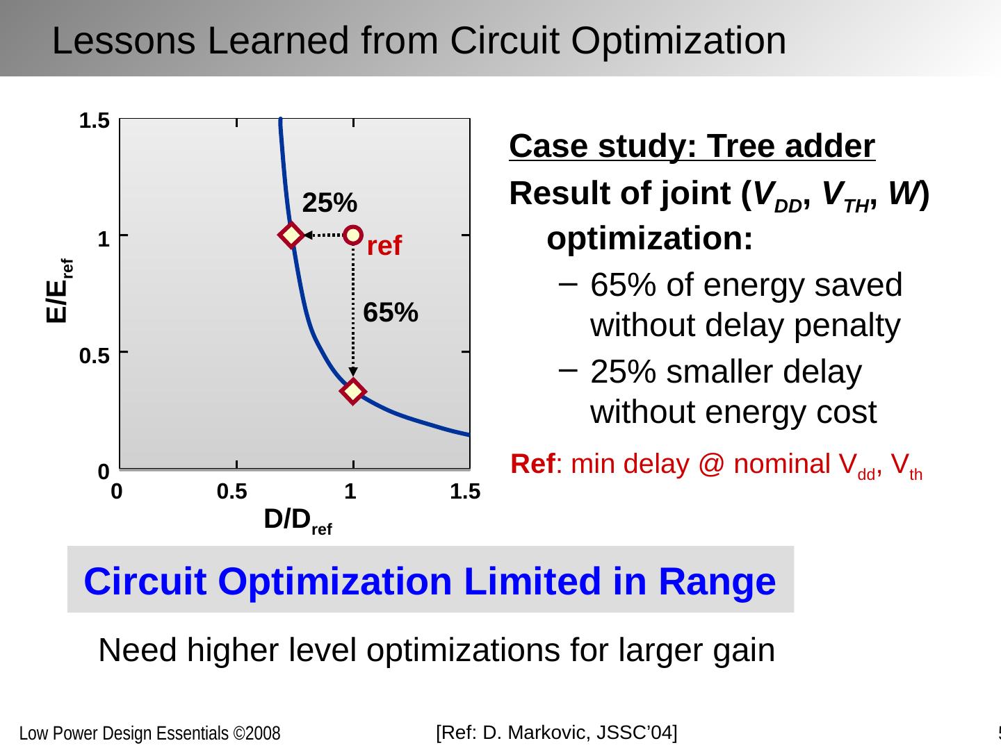
4 .[Ref: D. Markovic , JSSC’04] Circuit Optimization Limited in Range Case study: Tree adder Result of joint ( V DD , V TH , W ) optimization: 65% of energy saved without delay penalty 25% smaller delay without energy cost Need higher level optimizations for larger gain Lessons Learned from Circuit Optimization D/D ref E/E ref 0 0.5 1 1.5 1.5 1 0.5 0 65% ref Ref : min delay @ nominal V dd , V th 25 %
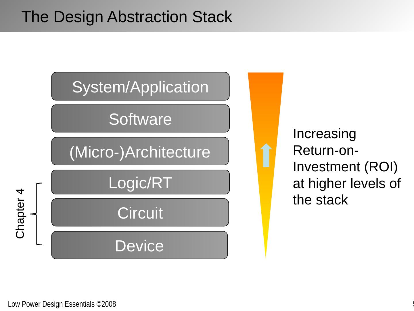
5 .Logic/RT (Micro-)Architecture Software Circuit Device System/Application Increasing Return-on-Investment (ROI) at higher levels of the stack Chapter 4 The Design Abstraction Stack
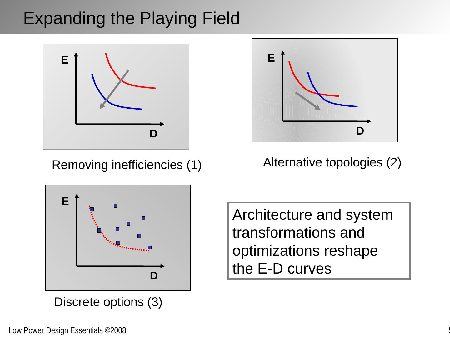
6 .Removing inefficiencies (1) Discrete options (3) Alternative topologies (2) D E D E D E Architecture and system transformations and optimizations reshape the E-D curves Expanding the Playing Field
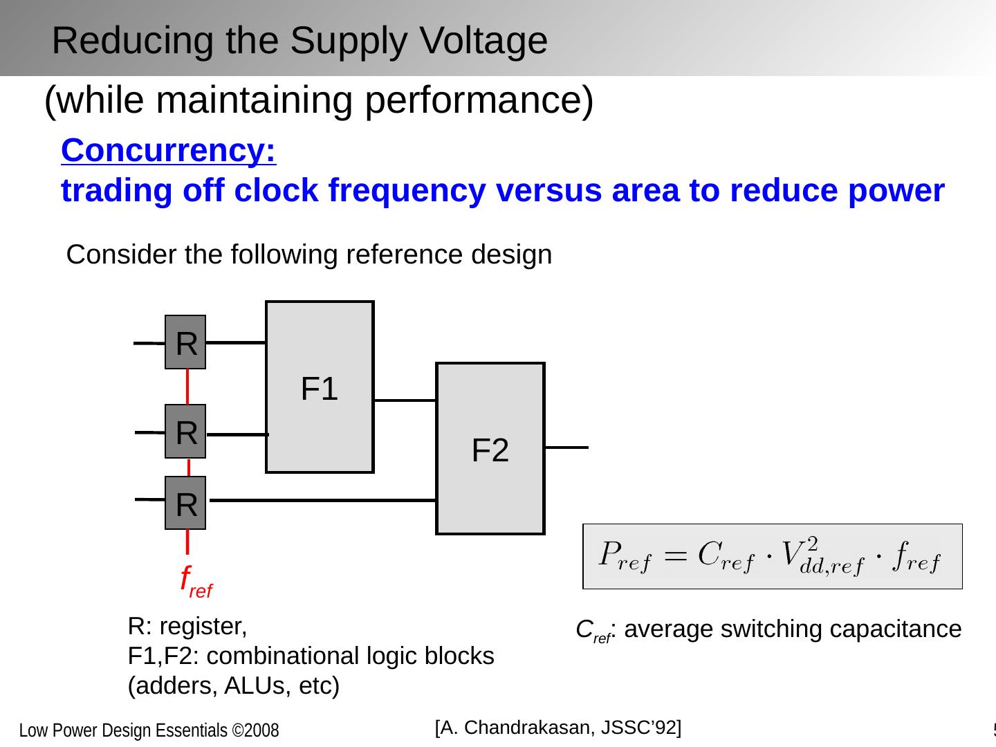
7 .(while maintaining performance) Concurrency: trading off clock frequency versus area to reduce power F1 Consider the following reference design F2 R R R f ref R: register, F1,F2: combinational logic blocks (adders, ALUs, etc) C ref : average switching capacitance [A. Chandrakasan , JSSC’92] Reducing the Supply Voltage
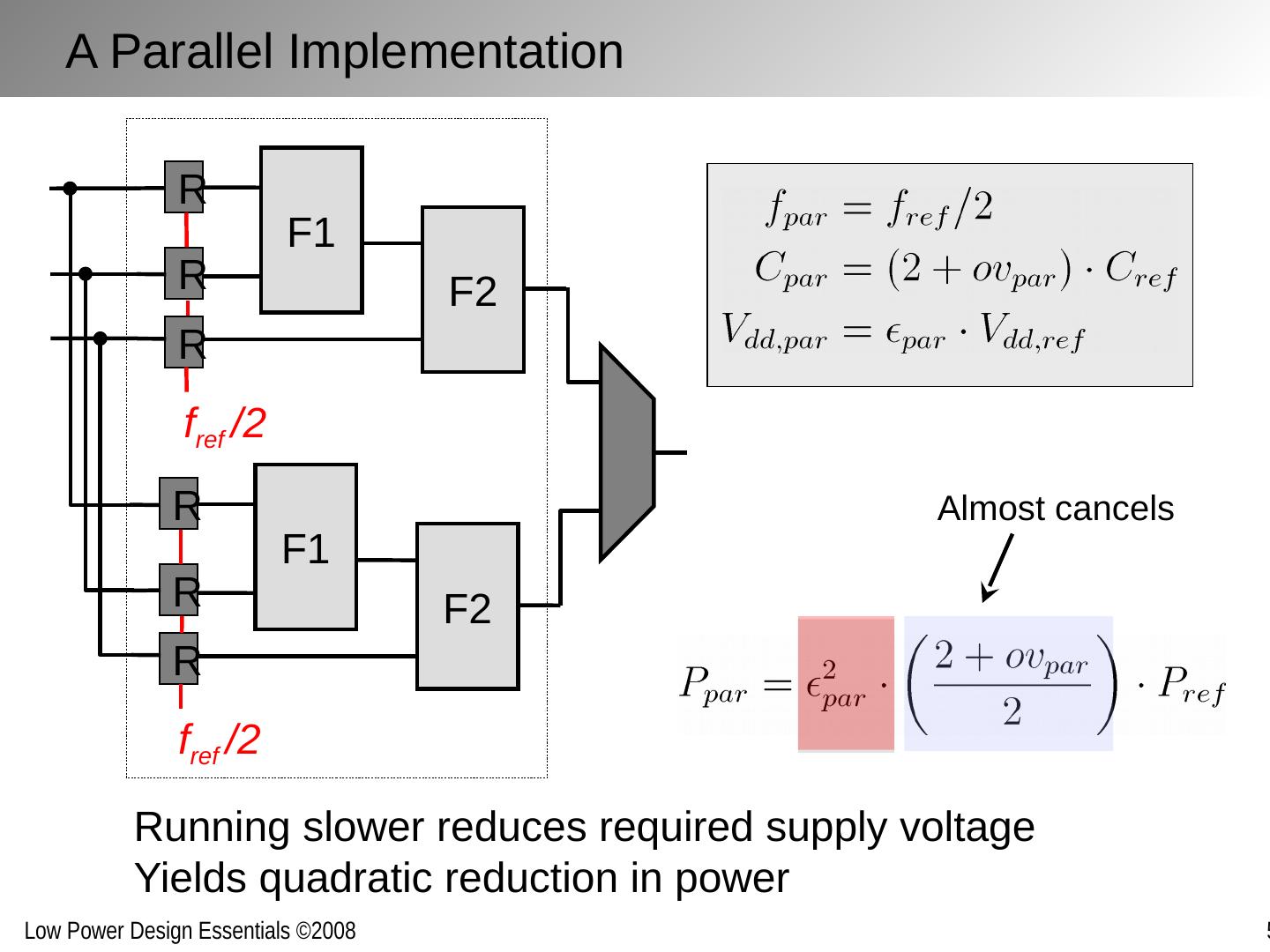
8 .F1 F2 R R R f ref /2 F1 F2 R R R f ref /2 Running slower reduces required supply voltage Yields quadratic reduction in power Almost cancels A Parallel Implementation
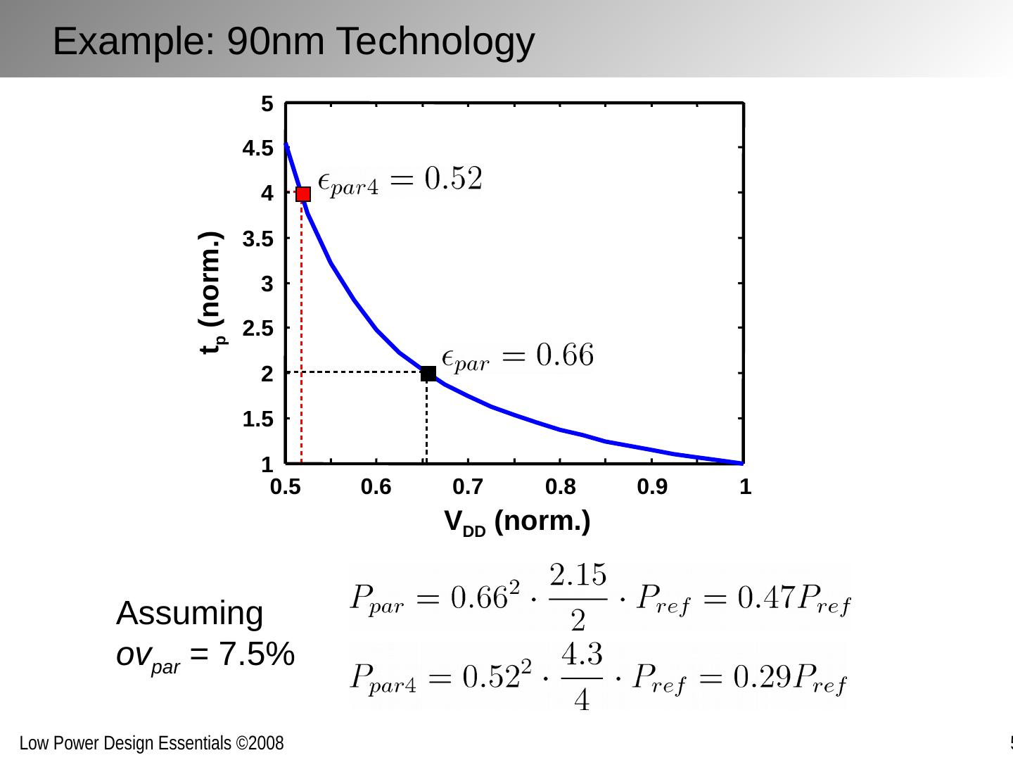
9 .Assuming ov par = 7.5% Example: 90nm Technology 0.5 0.6 0.7 0.8 0.9 1 1 1.5 2 2.5 3 3.5 4 4.5 5 V DD (norm.) t p (norm.)
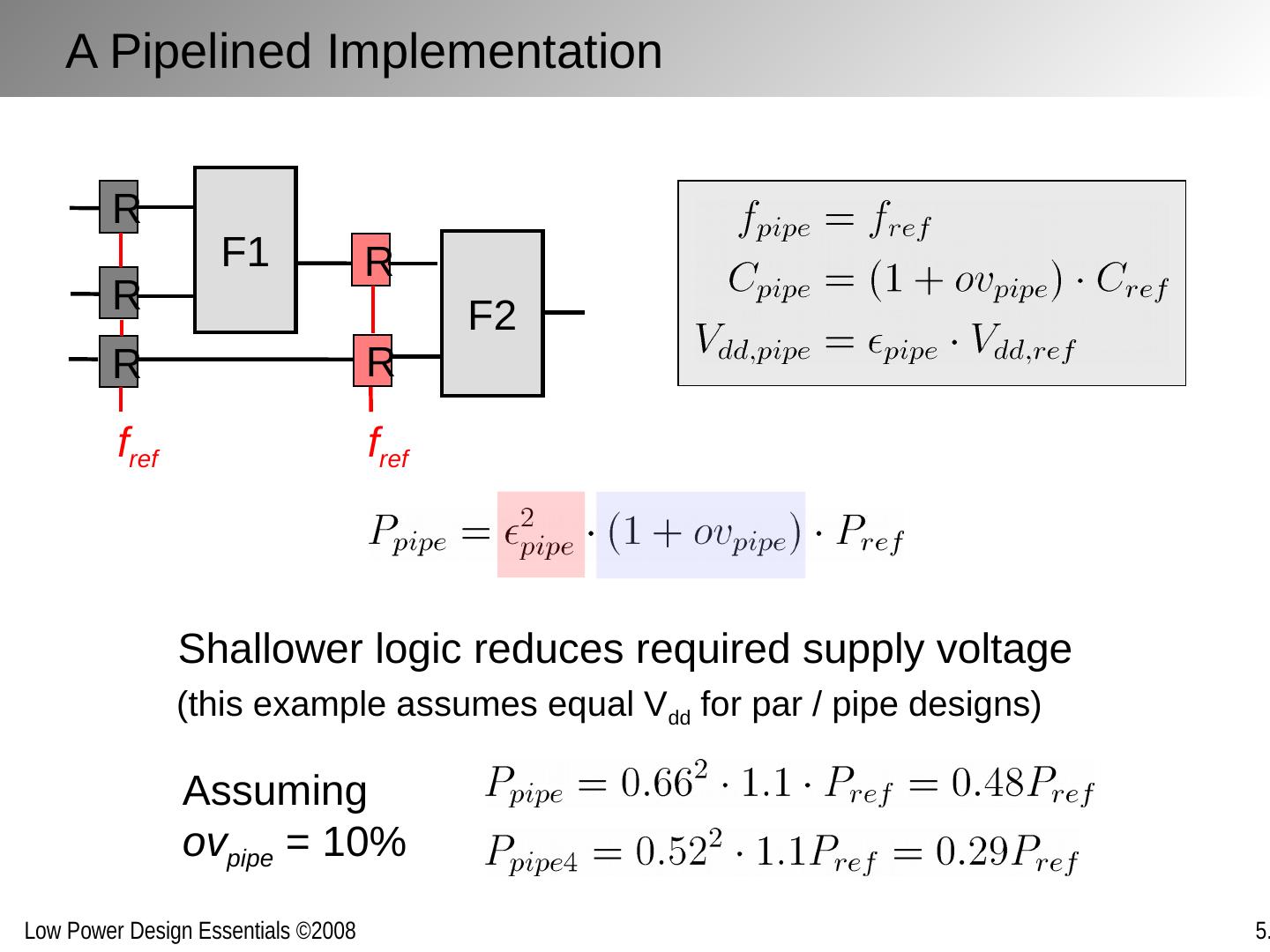
10 .F1 F2 R R R f ref R R f ref Assuming ov pipe = 10% Shallower logic reduces required supply voltage A Pipelined Implementation (this example assumes equal V dd for par / pipe designs)
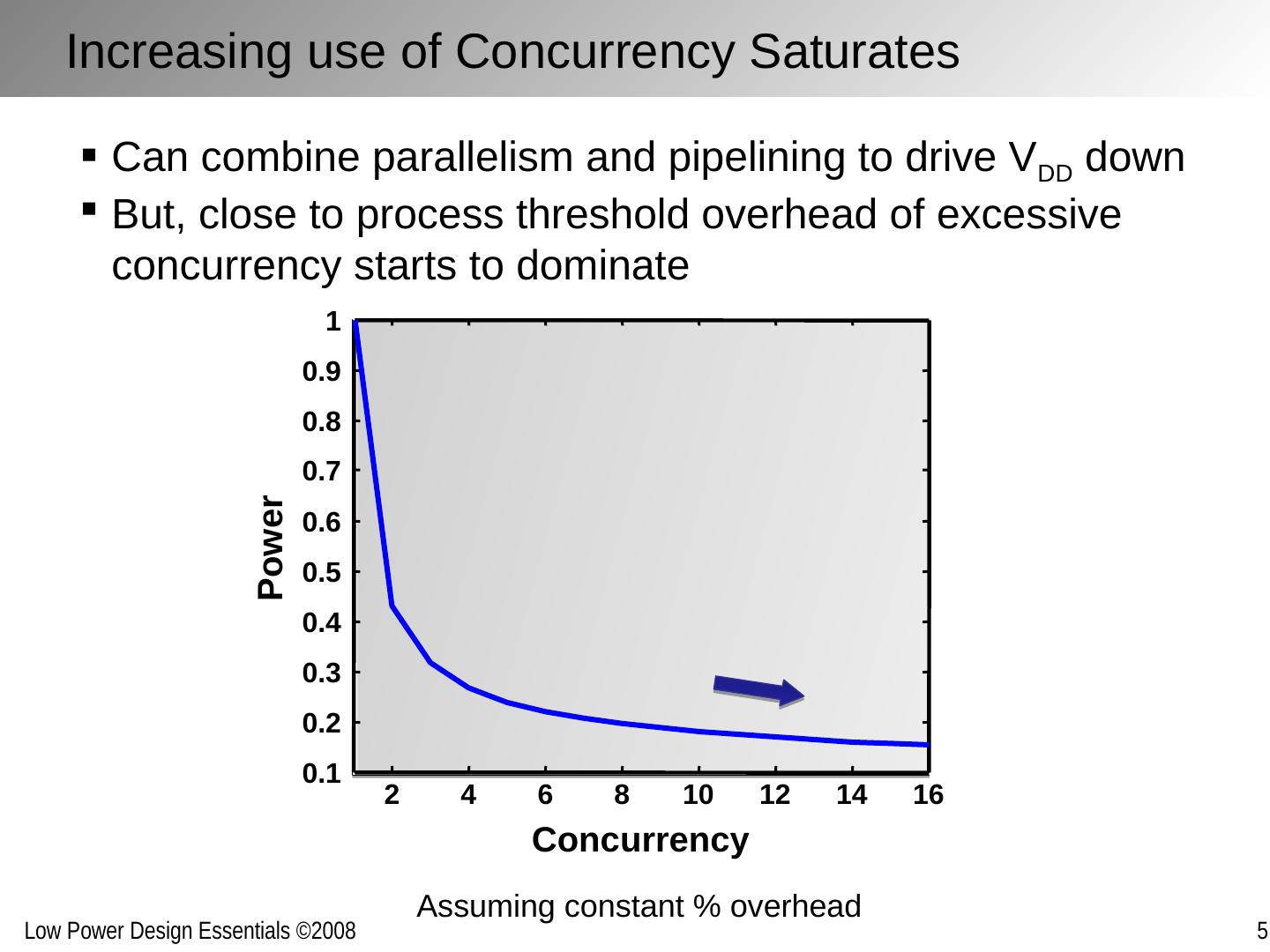
11 .Can combine parallelism and pipelining to drive V DD down But, close to process threshold overhead of excessive concurrency starts to dominate Assuming constant % overhead Increasing use of Concurrency Saturates 2 4 6 8 10 12 14 16 0.1 0.2 0.3 0.4 0.5 0.6 0.7 0.8 0.9 1 Concurrency Power
12 .P Fixed Throughput V DD Concurrency Nominal design (no concurrency) P min Only option: Reduce V TH as well! But: Must consider Leakage … Overhead + leakage Increasing use of Concurrency Saturates
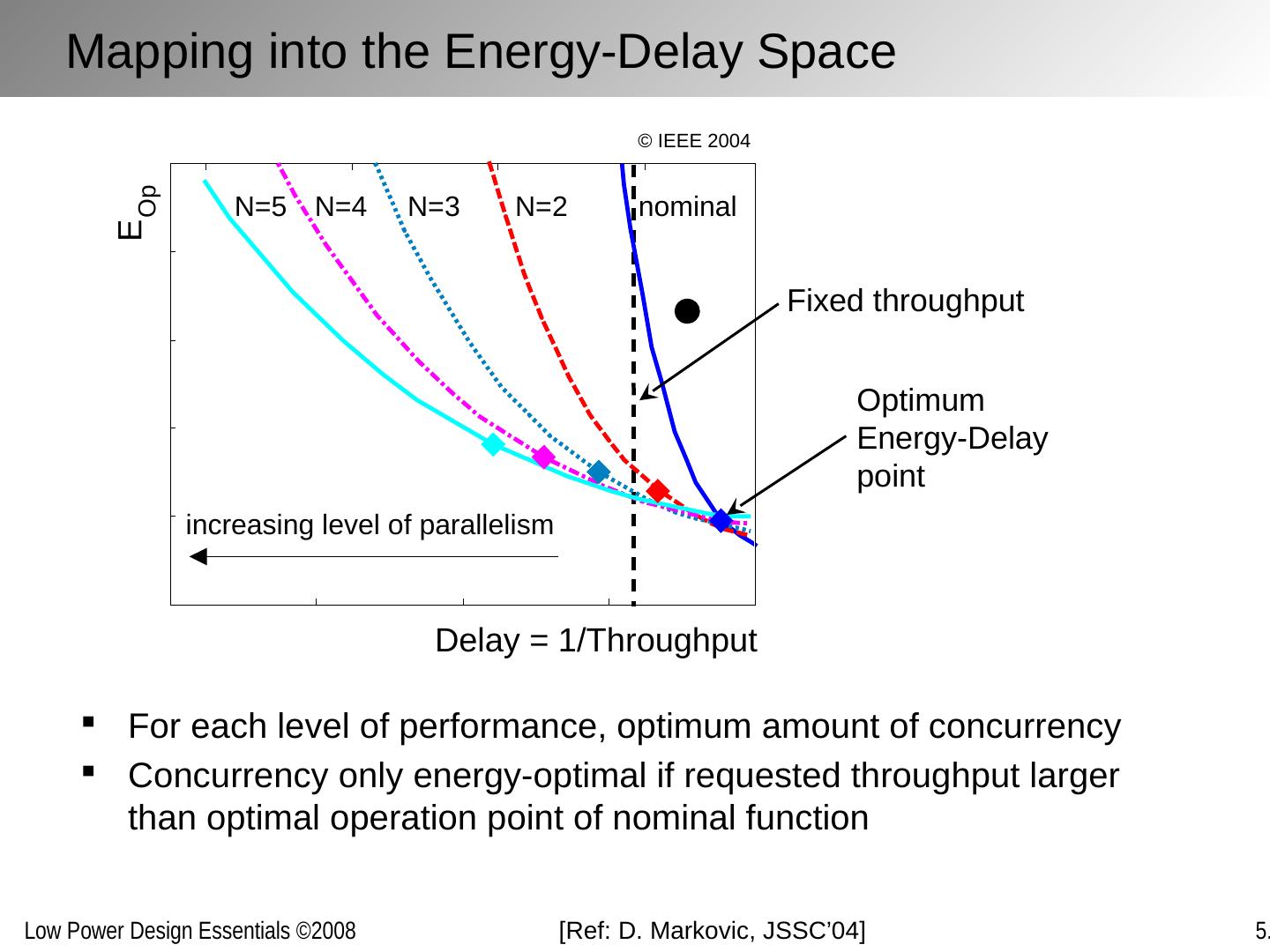
13 .Delay = 1/Throughput E Op nominal N=2 N=3 N=4 N=5 increasing level of parallelism Fixed throughput Optimum Energy-Delay point Mapping into the Energy-Delay Space For each level of performance, optimum amount of concurrency Concurrency only energy-optimal if requested throughput larger than optimal operation point of nominal function [Ref: D. Markovic , JSSC’04] © IEEE 2004
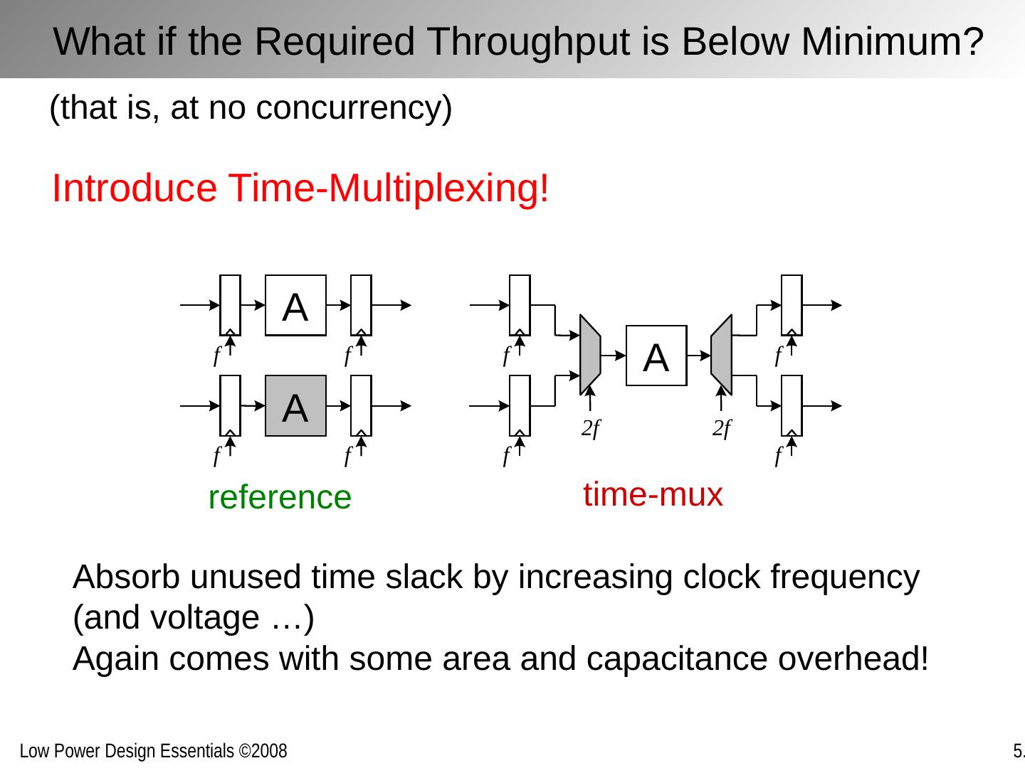
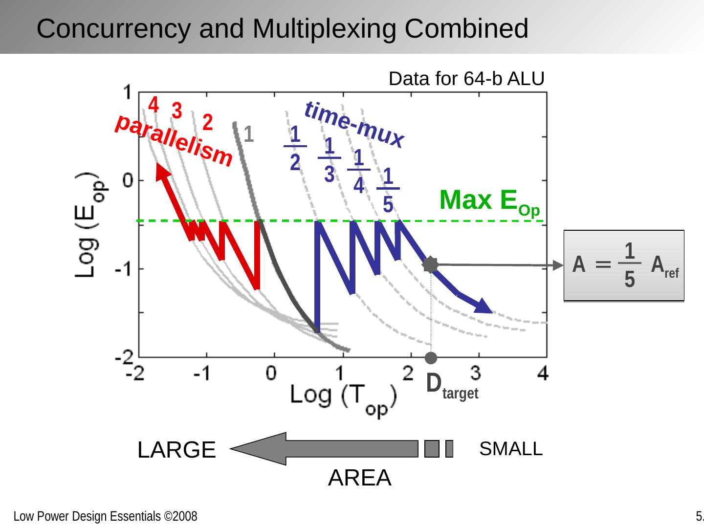
14 .time-mux reference Introduce Time-Multiplexing! A f f A f f A f f f f 2 f 2 f (that is, at no concurrency) Absorb unused time slack by increasing clock frequency (and voltage …) Again comes with some area and capacitance overhead! What if the Required Throughput is Below Minimum?
15 .Max E Op 1 1 2 1 3 1 4 1 5 2 3 4 D target A = A ref 1 5 Data for 64-b ALU parallelism time-mux AREA SMALL LARGE Concurrency and Multiplexing Combined
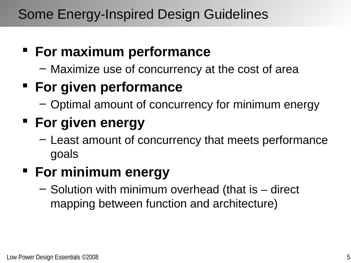
16 .For maximum performance Maximize use of concurrency at the cost of area For given performance Optimal amount of concurrency for minimum energy For given energy Least amount of concurrency that meets performance goals For minimum energy Solution with minimum overhead (that is – direct mapping between function and architecture) Some Energy-Inspired Design Guidelines
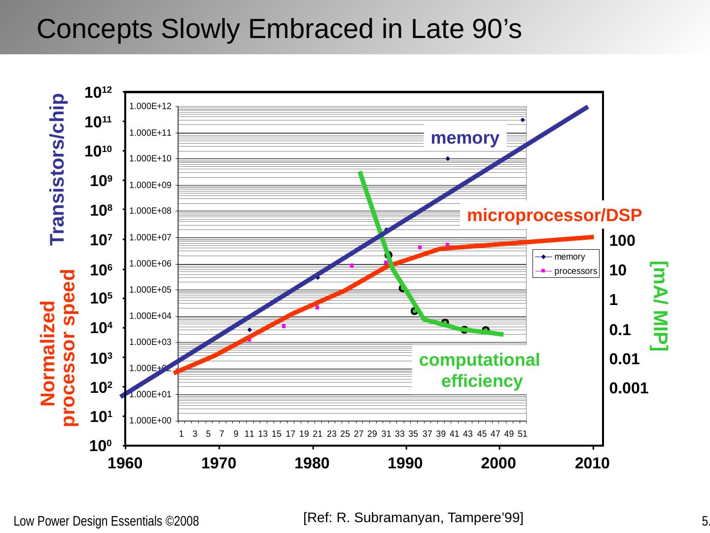
17 .[Ref: R. Subramanyan , Tampere’99] Concepts Slowly Embraced in Late 90’s Normalized processor speed [mA/ MIP] computational efficiency memory Transistors/chip 10 3 10 4 10 5 10 6 10 7 10 8 10 9 10 10 10 11 10 12 10 2 10 1 10 0 1960 1970 1980 1990 2000 2010 0.001 0.01 0.1 1 10 100 microprocessor/DSP
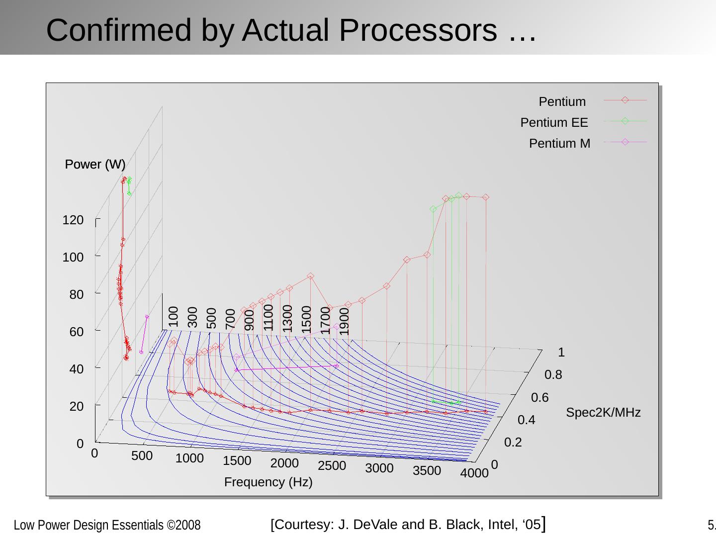
18 . Confirmed by Actual Processors … 0 500 1000 1500 2000 2500 3000 3500 4000 0 0.2 0.4 0.6 0.8 1 0 20 40 60 80 100 120 Power (W) 100 300 500 700 900 1100 1300 1500 1700 1900 Pentium Pentium EE Pentium M Frequency (Hz) Spec2K/MHz Power (W) [ Courtesy : J. DeVale and B. Black, Intel, ‘05 ]
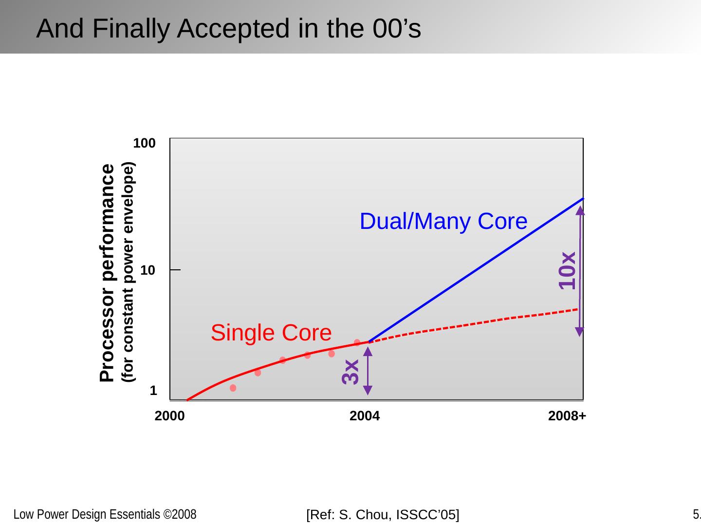
19 .[Ref: S . Chou, ISSCC’05 ] 2000 2008+ 2004 1 10 100 Processor performance (for constant power envelope) 10x 3x Single Core Dual/Many Core And Finally Accepted in the 00’s
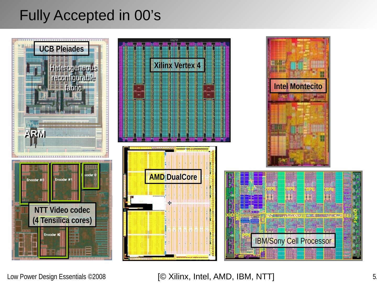
20 .Xilinx Vertex 4 IBM/Sony Cell Processor Intel Montecito ARM Heterogeneous reconfigurable fabric UCB Pleiades NTT Video codec (4 Tensilica cores) AMD DualCore Fully Accepted in 00’s [© Xilinx, Intel, AMD, IBM, NTT]
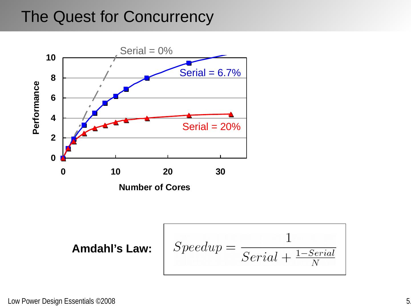
21 .Amdahl’s Law: Serial = 6.7% Serial = 20% Serial = 0% The Quest for Concurrency
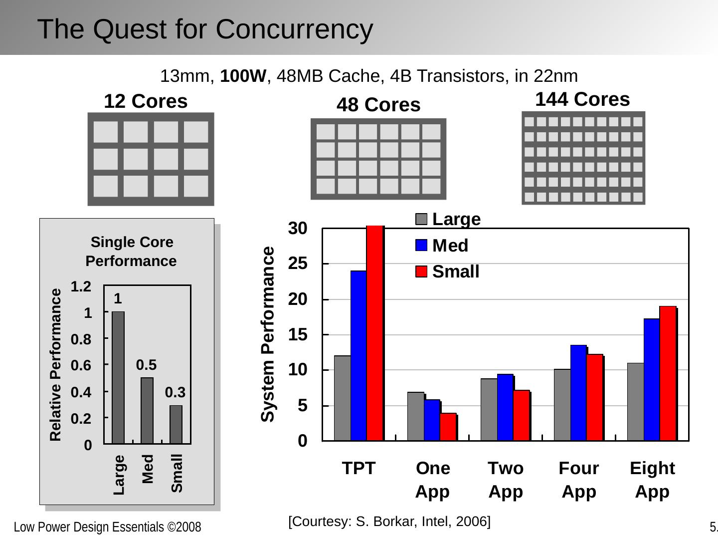
22 .13mm, 100W , 48MB Cache, 4B Transistors, in 22nm 12 Cores 48 Cores 144 Cores Single Core Performance 1 0.5 0.3 0 0.2 0.4 0.6 0.8 1 1.2 Large Med Small Relative Performance [Courtesy: S. Borkar , Intel, 2006] The Quest for Concurrency
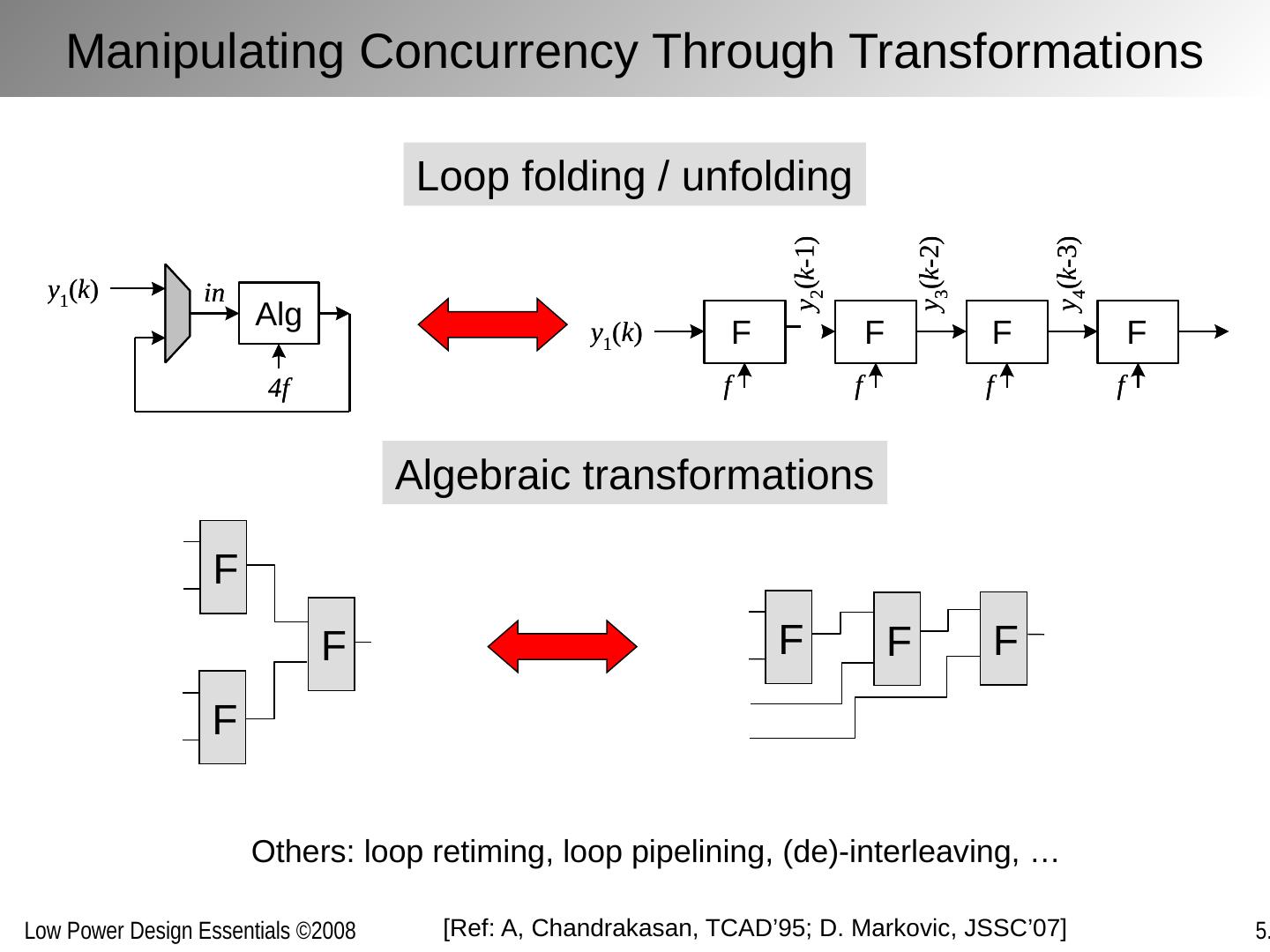
23 .[Ref: A, Chandrakasan , TCAD’95; D. Markovic , JSSC’07] Loop folding / unfolding Others: loop retiming, loop pipelining, (de)-interleaving, … Algebraic transformations F F F F F F Manipulating Concurrency Through Transformations
24 .Example: Visualizing MPEG-4 encoder Parallelism [Courtesy: W.M. Hwu , Illinois] Concurrent Compilers to Pick Up the Pace
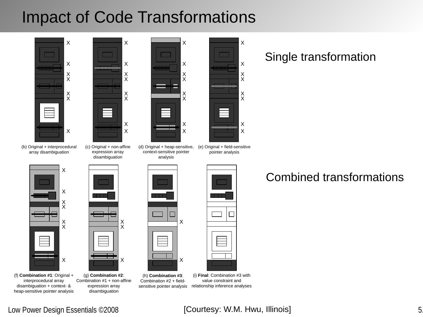
25 .Single transformation Combined transformations [Courtesy: W.M. Hwu , Illinois] Impact of Code Transformations
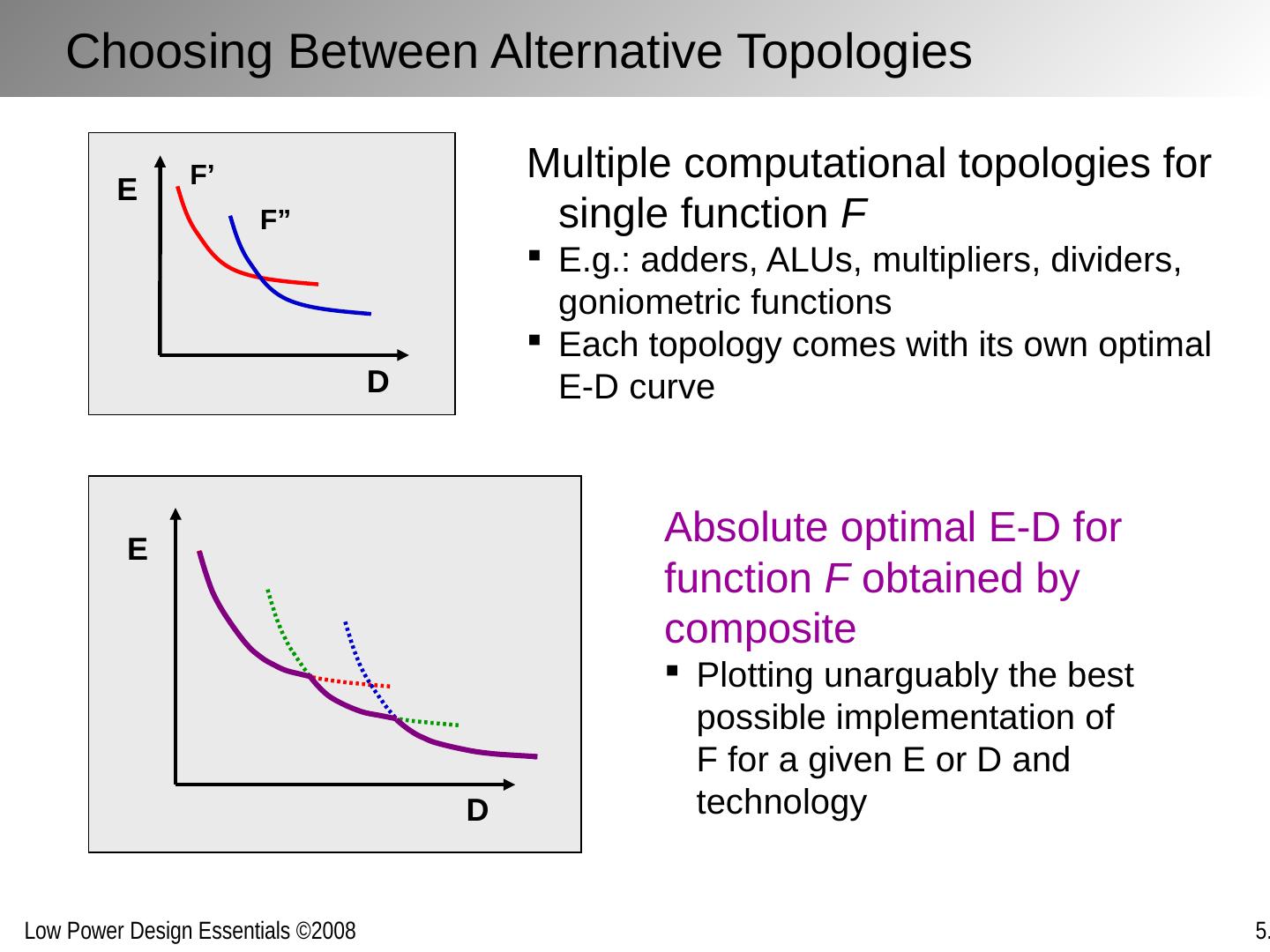
26 .D E D E F’ F” Choosing Between Alternative Topologies Multiple computational topologies for single function F E.g.: adders, ALUs, multipliers, dividers, goniometric functions Each topology comes with its own optimal E-D curve Absolute optimal E-D for function F obtained by composite Plotting unarguably the best possible implementation of F for a given E or D and technology
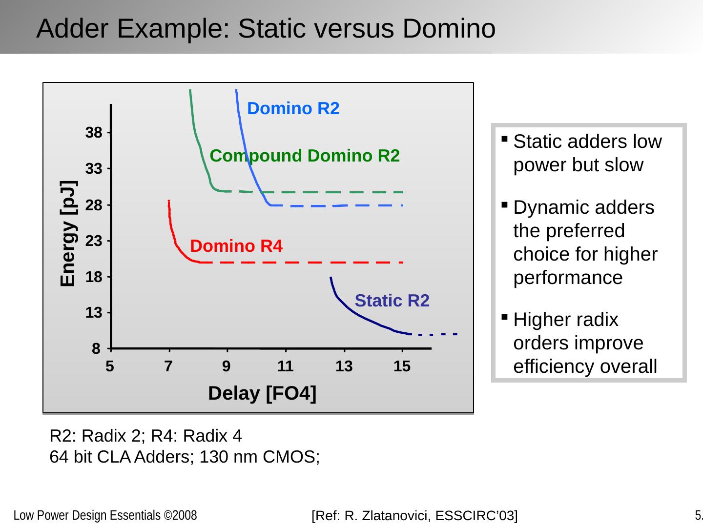
27 .R2: Radix 2; R4: Radix 4 64 bit CLA Adders; 130 nm CMOS; Static adders low power but slow Dynamic adders the preferred choice for higher performance Higher radix orders improve efficiency overall [Ref: R. Zlatanovici , ESSCIRC’03] Adder Example: Static versus Domino Static R2 Domino R4 Domino R2 Compound Domino R2 8 13 18 23 28 33 38 5 7 9 11 13 15 Delay [FO4] Energy [pJ]
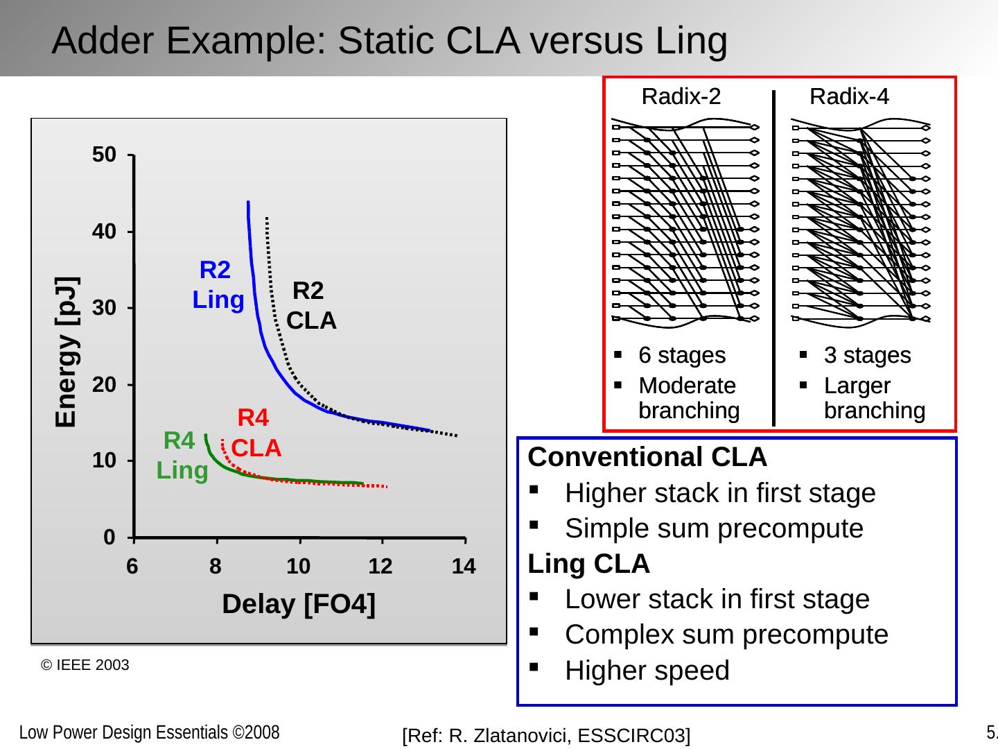
28 .Conventional CLA Higher stack in first stage Simple sum precompute Ling CLA Lower stack in first stage Complex sum precompute Higher speed Adder Example: Static CLA versus Ling 0 10 20 30 40 50 6 8 10 12 14 Delay [FO4] Energy [pJ] R2 Ling R2 CLA R4 CLA R4 Ling [Ref: R. Zlatanovici , ESSCIRC03] © IEEE 2003
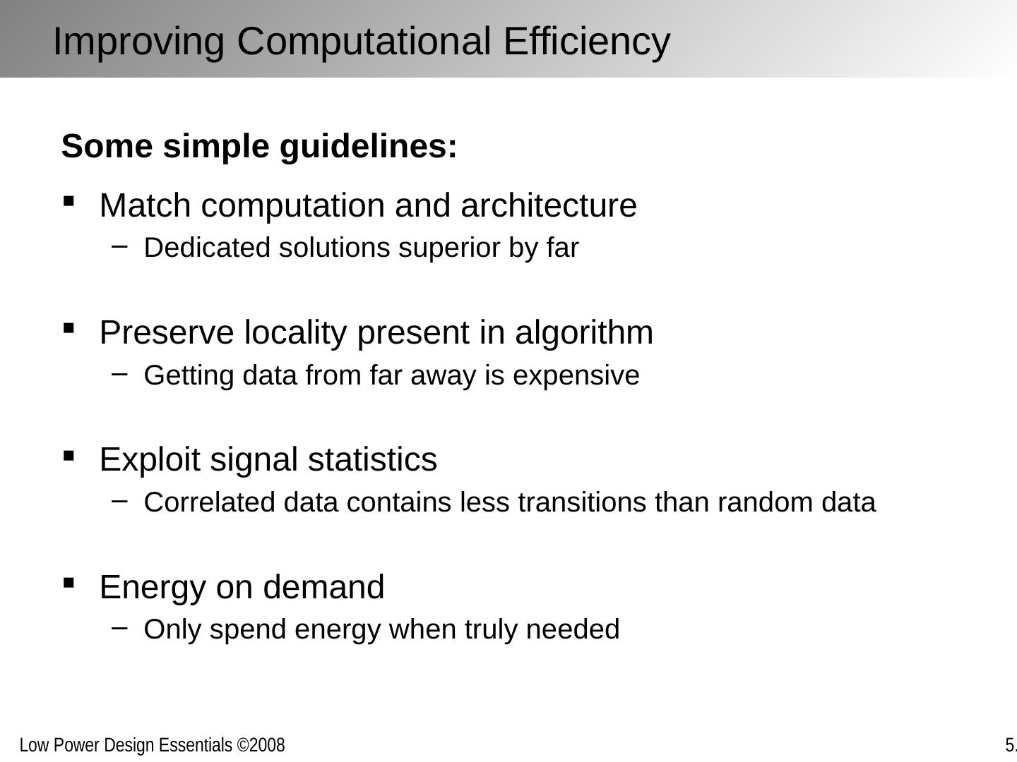
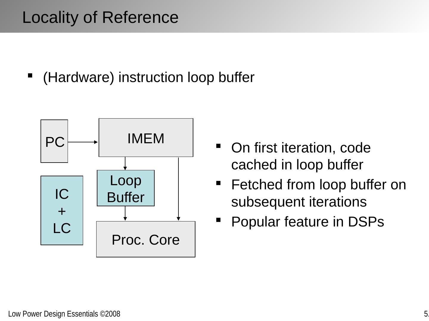
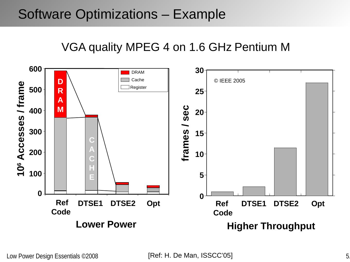
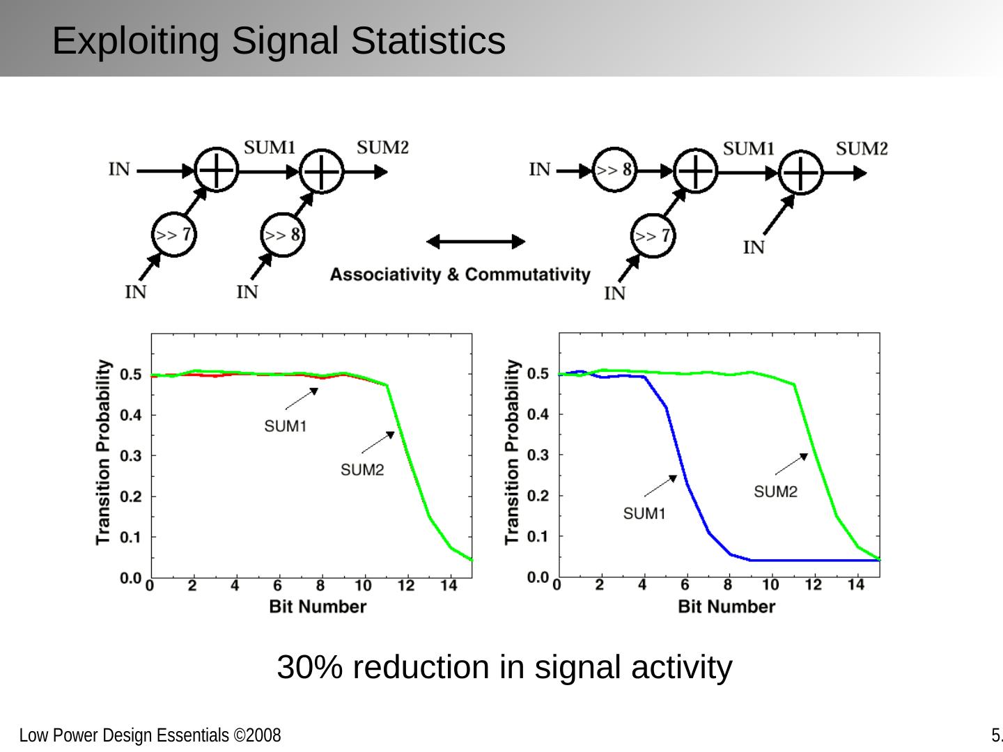
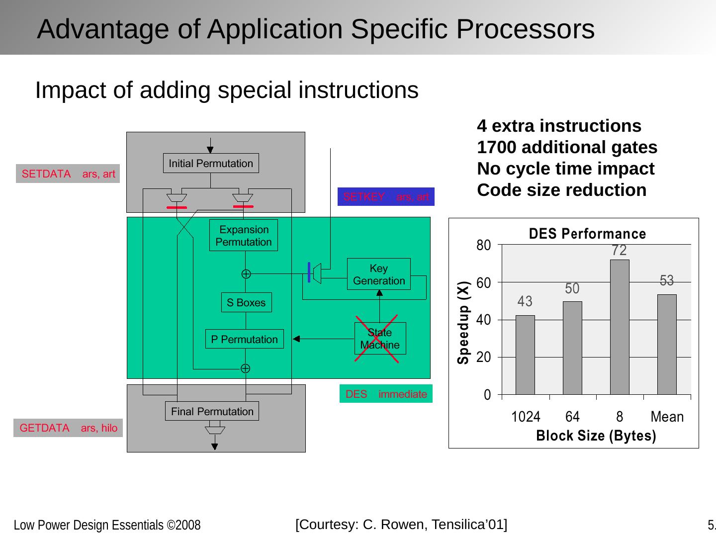
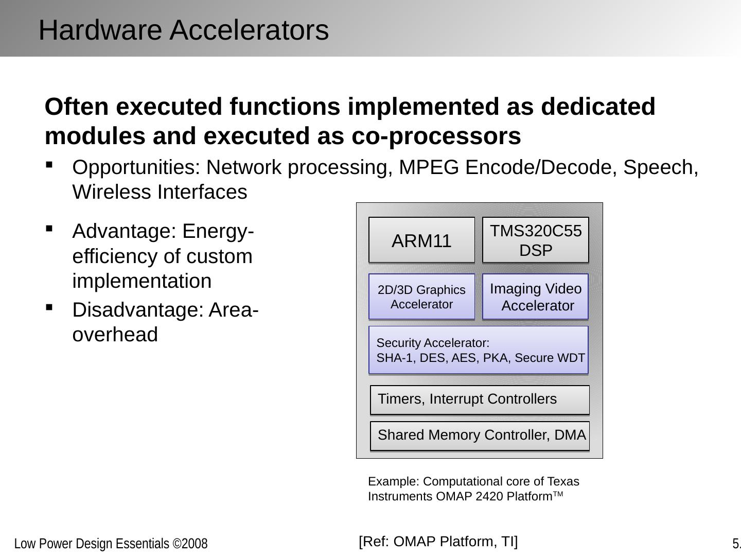
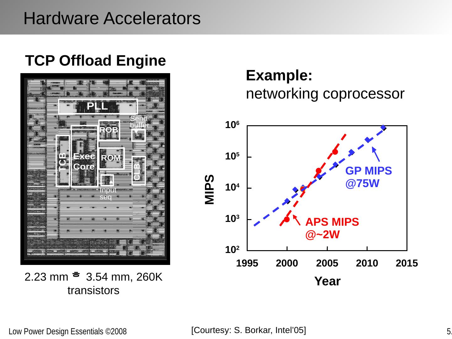
29 .D E Implementations for a given function maybe inefficient and can often be replaced with more efficient versions without penalty in energy or delay Improving Computational Efficiency Inefficiencies arise from: Over-dimensioning or over-design Generality of function Design methodologies Limited design time Need for flexibility, re-use and programmability


