- 快召唤伙伴们来围观吧
- 微博 QQ QQ空间 贴吧
- 文档嵌入链接
- 复制
- 微信扫一扫分享
- 已成功复制到剪贴板
电容,氧化物电荷对金属氧化物电容器的影响
展开查看详情
1 . Lecture #22 OUTLINE The MOS Capacitor • Capacitance • Effect of Oxide Charges Reading: Course Reader (Part III, Chap. 2) Spring 2003 EE130 Lecture 22, Slide 1 Review: Threshold Voltage • For p-type Si (“NMOS”): 2qN Aε Si (2ψ B ) VT = VFB + 2ψ B + Cox • For n-type Si (“PMOS”): 2qN Dε Si 2ψ B VT = VFB + 2ψ B − Cox Spring 2003 EE130 Lecture 22, Slide 2 1
2 . ψs and Wd vs. VG (p-type Si) 2φ F ψs: qN Aε si 2C (V − VFB ) 2 2 ψs = 1 + ox G − 1 (for VFB < VG < VT ) Aε si 2 2Cox qN 0 VG accumulation V depletion V inversion FB T 2ε Si (2ψ F ) Wdm = qN A Wd: 2ε Siψ S ε Si 2C (V − VFB ) 2 Wd = = 1 + ox G − 1 (for VFB < VG < VT ) qN A Cox qN Aε si 0 VG accumulation V depletion V inversion FB T Spring 2003 EE130 Lecture 22, Slide 3 Total Charge Density in Si, Qs Qacc = −Cox (VG − VFB ) depletion inversion 0 accumulation VG Qs = Qacc + Qdep + Qinv VFB VT accumulation depletion inversion accumulation depletion inversion 0 VG VFB VT VG Qdep = − qN AW 0 VFB VT accumulation depletion inversion 0 VG Qinv VFB VT slope = -Cox Qinv = −Cox (VG − VT ) Spring 2003 EE130 Lecture 22, Slide 4 2
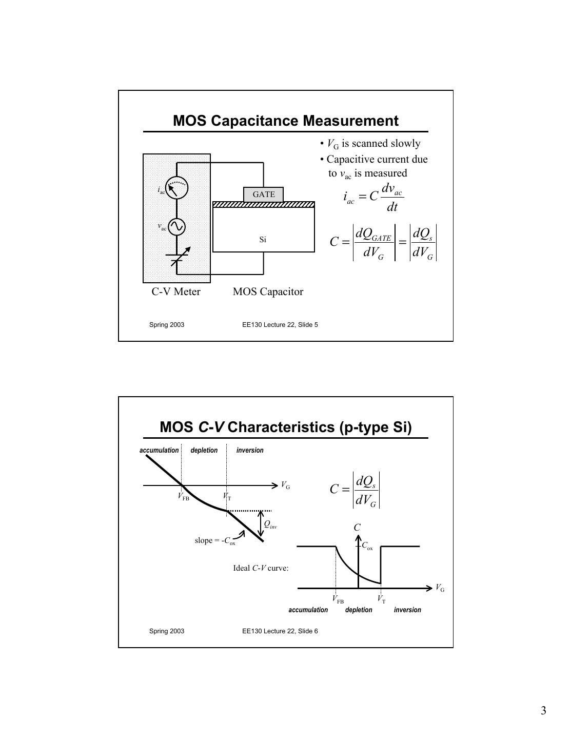
3 . MOS Capacitance Measurement • VG is scanned slowly • Capacitive current due to vac is measured iac dvac GATE iac = C dt vac dQGATE dQs Si C= = dVG dVG C-V Meter MOS Capacitor Spring 2003 EE130 Lecture 22, Slide 5 MOS C-V Characteristics (p-type Si) accumulation depletion inversion VG dQs VFB VT C= dVG Qinv C slope = -Cox Cox Ideal C-V curve: VG VFB VT accumulation depletion inversion Spring 2003 EE130 Lecture 22, Slide 6 3
4 .Capacitance in Accumulation (p-type Si) • As the gate voltage is varied, incremental charge is added/subtracted to/from the gate and substrate. • The incremental charges are separated by the gate oxide. M O S ∆Q Q dQacc C= = Cox -Q dVG −∆Q Cox Spring 2003 EE130 Lecture 22, Slide 7 Flat-Band Capacitance • At the flat-band condition, variations in VG give rise to the addition/subtraction of incremental charge in the substrate, at a depth LD • LD is the “extrinsic Debye Length” – characteristic shielding distance, or the distance where the electric field emanating from a perturbing charge falls off by a factor of 1/e ε Si kT LD = q2 N A 1 1 L = + D CFB Cox ε Si Spring 2003 EE130 Lecture 22, Slide 8 4
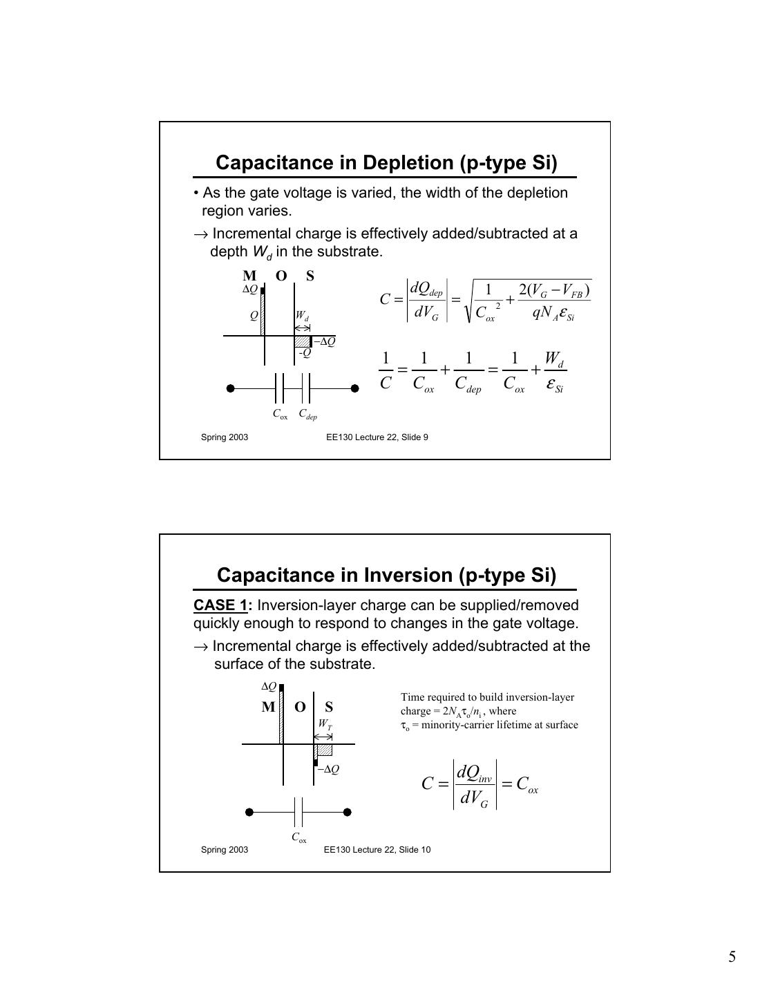
5 . Capacitance in Depletion (p-type Si) • As the gate voltage is varied, the width of the depletion region varies. → Incremental charge is effectively added/subtracted at a depth Wd in the substrate. M O S ∆Q dQdep 1 2(VG − VFB ) C= = + Q Wd dVG Cox 2 qN Aε Si −∆Q -Q 1 1 1 1 Wd = + = + C Cox Cdep Cox ε Si Cox Cdep Spring 2003 EE130 Lecture 22, Slide 9 Capacitance in Inversion (p-type Si) CASE 1: Inversion-layer charge can be supplied/removed quickly enough to respond to changes in the gate voltage. → Incremental charge is effectively added/subtracted at the surface of the substrate. ∆Q Time required to build inversion-layer M O S charge = 2NAτo/ni , where WT τo = minority-carrier lifetime at surface −∆Q dQinv C= = Cox dVG Cox Spring 2003 EE130 Lecture 22, Slide 10 5
6 . Capacitance in Inversion (p-type Si) CASE 2: Inversion-layer charge cannot be supplied/removed quickly enough to respond to changes in the gate voltage. → Incremental charge is effectively added/subtracted at a depth Wd in the substrate. ∆Q 1 1 1 = + M O S C Cox Cdep Wdm 1 Wdm −∆Q = + Cox ε Si 1 2(2ψ B ) 1 = + ≡ Cox Cdep Cox qN Aε Si C min Spring 2003 EE130 Lecture 22, Slide 11 Supply of Substrate Charge (p-type Si) gate gate Accumulation: Cox Depletion: Cox + + + + + + C dep Wd p-type Si p-type Si Case 1 Case 2 Inversion: gate gate Cox Cox N+ - - - - - - DC - - - - - - Cdep,min - AC DC and AC Wdm WT p-type Si p-type Si Spring 2003 EE130 Lecture 22, Slide 12 6
7 . Capacitor vs. Transistor C-V (or LF vs. HF C-V) p-type Si: C MOS transistor at any f, MOS capacitor at low f, or quasi-static C-V Cmax=Cox CFB MOS capacitor at high f Cmin VG accumulation depletion inversion VFB VT Spring 2003 EE130 Lecture 22, Slide 13 Quasi-Static C-V Measurement p-type Si: C Cmax=Cox CFB Cmin VG accumulation depletion inversion VFB VT The quasi-static C-V characteristic is obtained by slowly ramping the gate voltage (< 0.1V/s), while measuring the gate current IG with a very sensitive DC ammeter. C is calculated from IG = C·dVG/dt. Spring 2003 EE130 Lecture 22, Slide 14 7
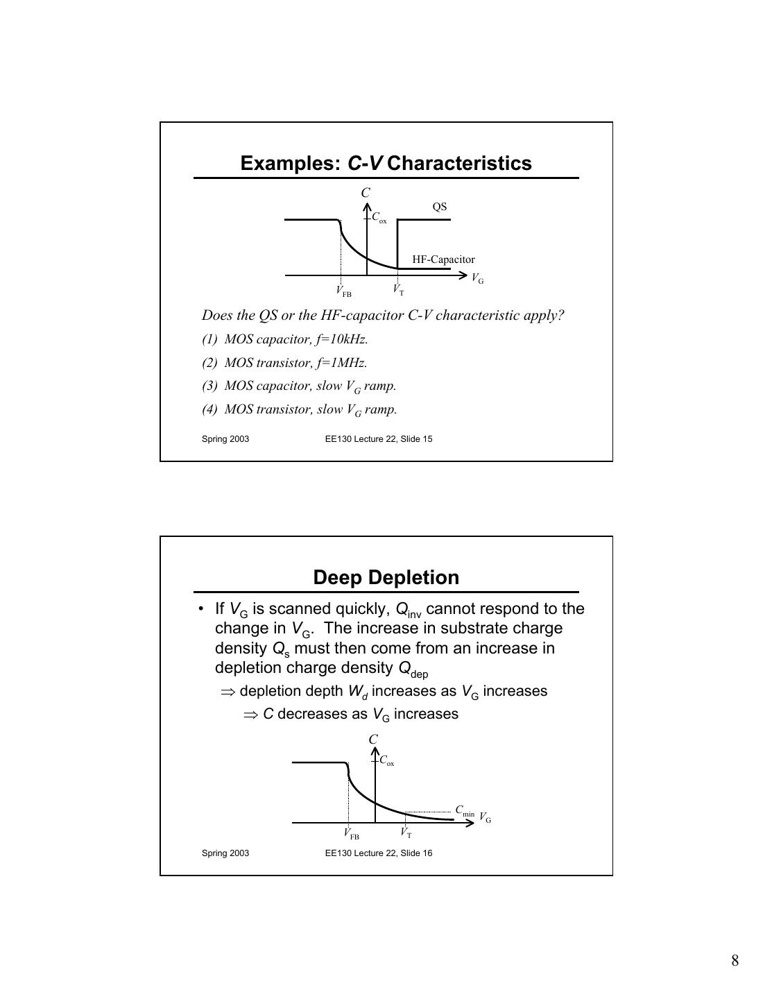
8 . Examples: C-V Characteristics C QS Cox HF-Capacitor VG VFB VT Does the QS or the HF-capacitor C-V characteristic apply? (1) MOS capacitor, f=10kHz. (2) MOS transistor, f=1MHz. (3) MOS capacitor, slow VG ramp. (4) MOS transistor, slow VG ramp. Spring 2003 EE130 Lecture 22, Slide 15 Deep Depletion • If VG is scanned quickly, Qinv cannot respond to the change in VG. The increase in substrate charge density Qs must then come from an increase in depletion charge density Qdep ⇒ depletion depth Wd increases as VG increases ⇒ C decreases as VG increases C Cox Cmin VG VFB VT Spring 2003 EE130 Lecture 22, Slide 16 8
9 . Parameter Extraction from C-V From a single C-V measurement, we can extract much information about the MOS device. • Suppose we know that the gate-electrode material is heavily doped n-type poly-Si (ΦM=4.05eV), and that the gate dielectric is SiO2 (εr=3.9): – From Cmax = Cox we determine the oxide thickness tox – From Cmin and Cox we determine substrate doping (by iteration) – From substrate doping and Cox we calculate the flat-band capacitance CFB – From the C-V curve, we can find VFB = VG C =C FB – From ΦM, ΦS, Cox, and VFB we can determine Qf Spring 2003 EE130 Lecture 22, Slide 17 Example: Effect of Doping C/Cox 1 VG VFB VT • How would C-V characteristic change if substrate doping NA were increased? – VFB – VT – Cmin Spring 2003 EE130 Lecture 22, Slide 18 9
10 . Example: Effect of Oxide Thickness C/Cox 1 VG VFB VT • How would C-V characteristic change if oxide thickness tox were decreased? – VFB – VT – Cmin Spring 2003 EE130 Lecture 22, Slide 19 Oxide Charges In real MOS devices, there is • In the oxide: always some charge in the oxide – Trapped charge Qot and at the Si/oxide interface. • High-energy electrons and/or holes injected into oxide – Mobile charge QM • Alkali-metal ions, which have sufficient mobility to drift in oxide under an applied electric field • At the interface: – Fixed charge QF • Excess Si (?) – Trapped charge Qit • Dangling bonds Spring 2003 EE130 Lecture 22, Slide 20 10
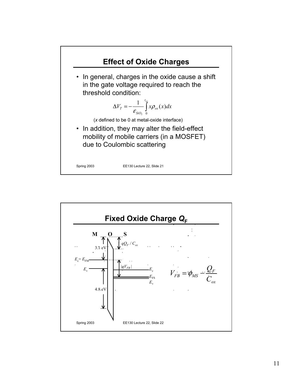
11 . Effect of Oxide Charges • In general, charges in the oxide cause a shift in the gate voltage required to reach the threshold condition: t ox 1 ∆VT = − ε SiO ∫ xρ 0 ox ( x)dx 2 (x defined to be 0 at metal-oxide interface) • In addition, they may alter the field-effect mobility of mobile carriers (in a MOSFET) due to Coulombic scattering Spring 2003 EE130 Lecture 22, Slide 21 Fixed Oxide Charge QF M O S qQF / Cox 3.1 eV Ec= EFM Ev |qVFB | Ec QF EFS VFB = φ MS − Ev Cox 4.8 eV Spring 2003 EE130 Lecture 22, Slide 22 11
12 . Determination of QF Measure C-V characteristics of capacitors with different oxide thicknesses. Plot VFB as a function of tox. VFB 10nm 20nm 30nm x ox 0 tox –0.15V VFB = φ MS − QF × ε SiO 2 × –0.3V × Spring 2003 EE130 Lecture 22, Slide 23 Mobile Ions • Odd shifts in C-V characteristics were once a mystery: QM ∆VFB = − Cox • Source of problem: Mobile charge moving to/away from interface, changing charge centroid Spring 2003 EE130 Lecture 22, Slide 24 12
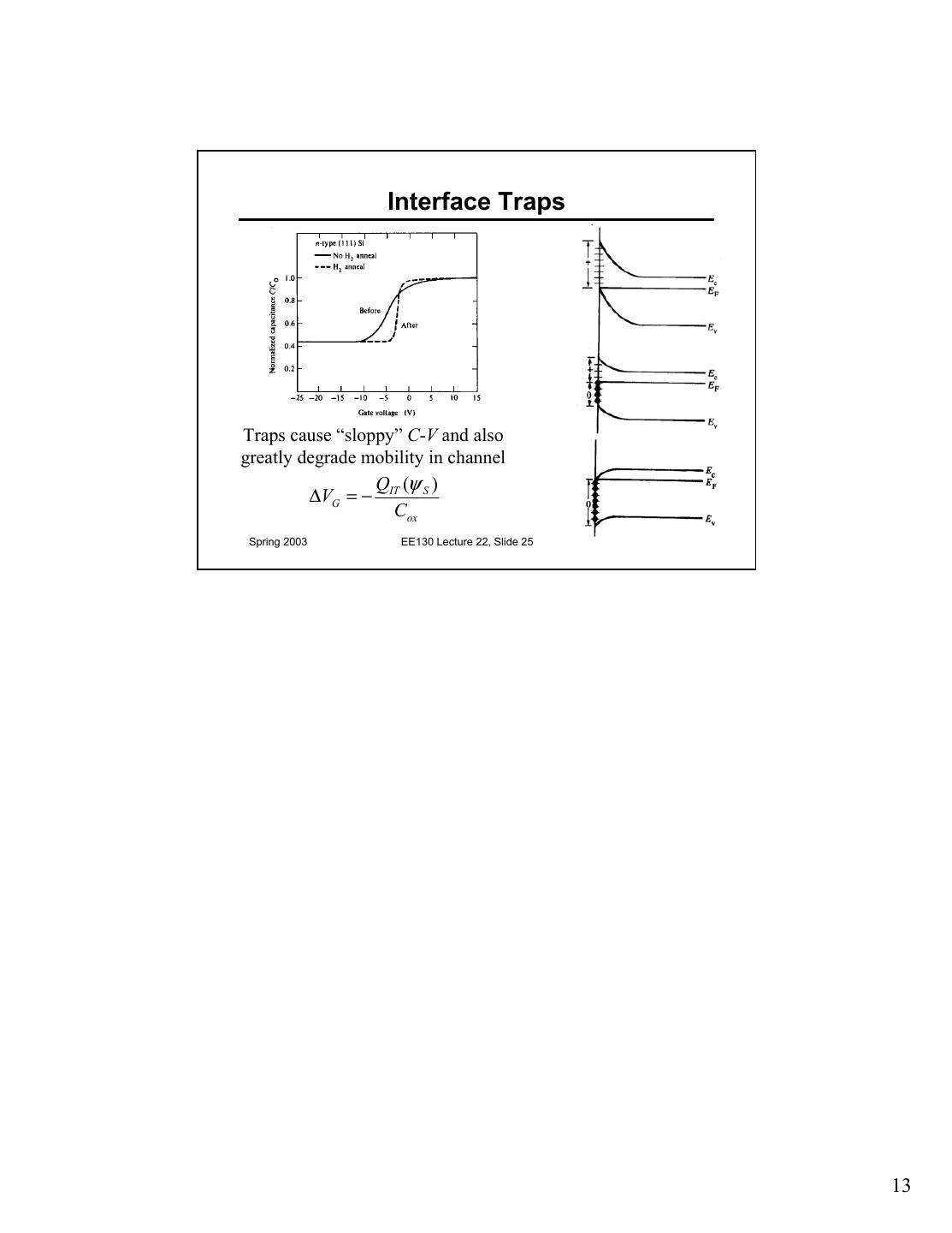
13 . Interface Traps Traps cause “sloppy” C-V and also greatly degrade mobility in channel Q (ψ ) ∆VG = − IT S Cox Spring 2003 EE130 Lecture 22, Slide 25 13


