- 快召唤伙伴们来围观吧
- 微博 QQ QQ空间 贴吧
- 文档嵌入链接
- 复制
- 微信扫一扫分享
- 已成功复制到剪贴板
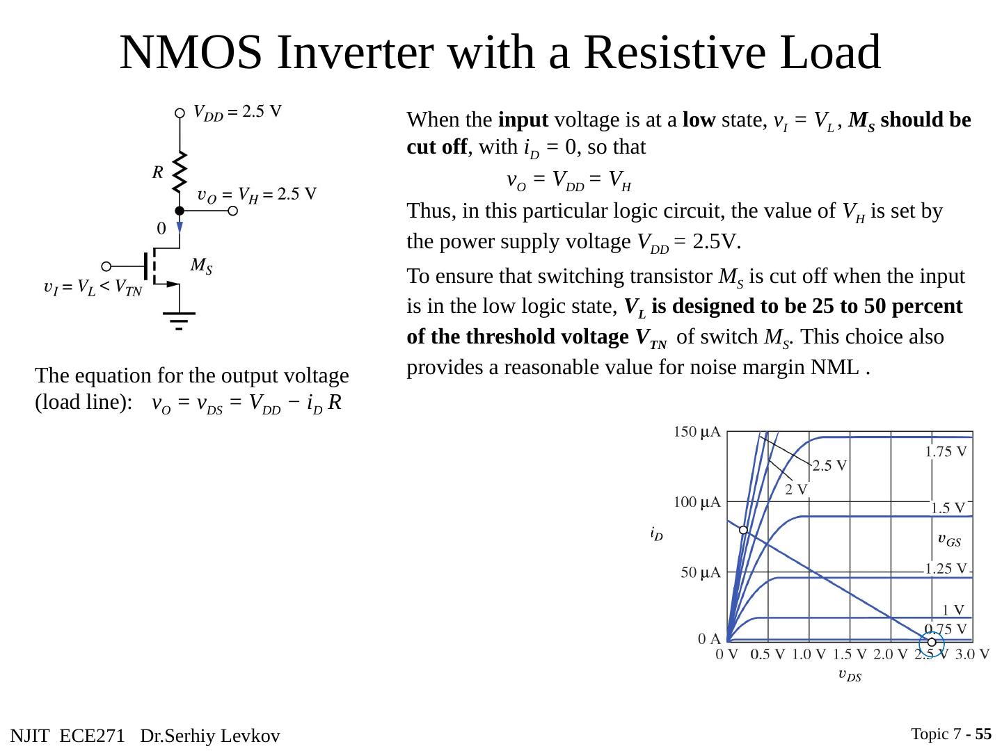
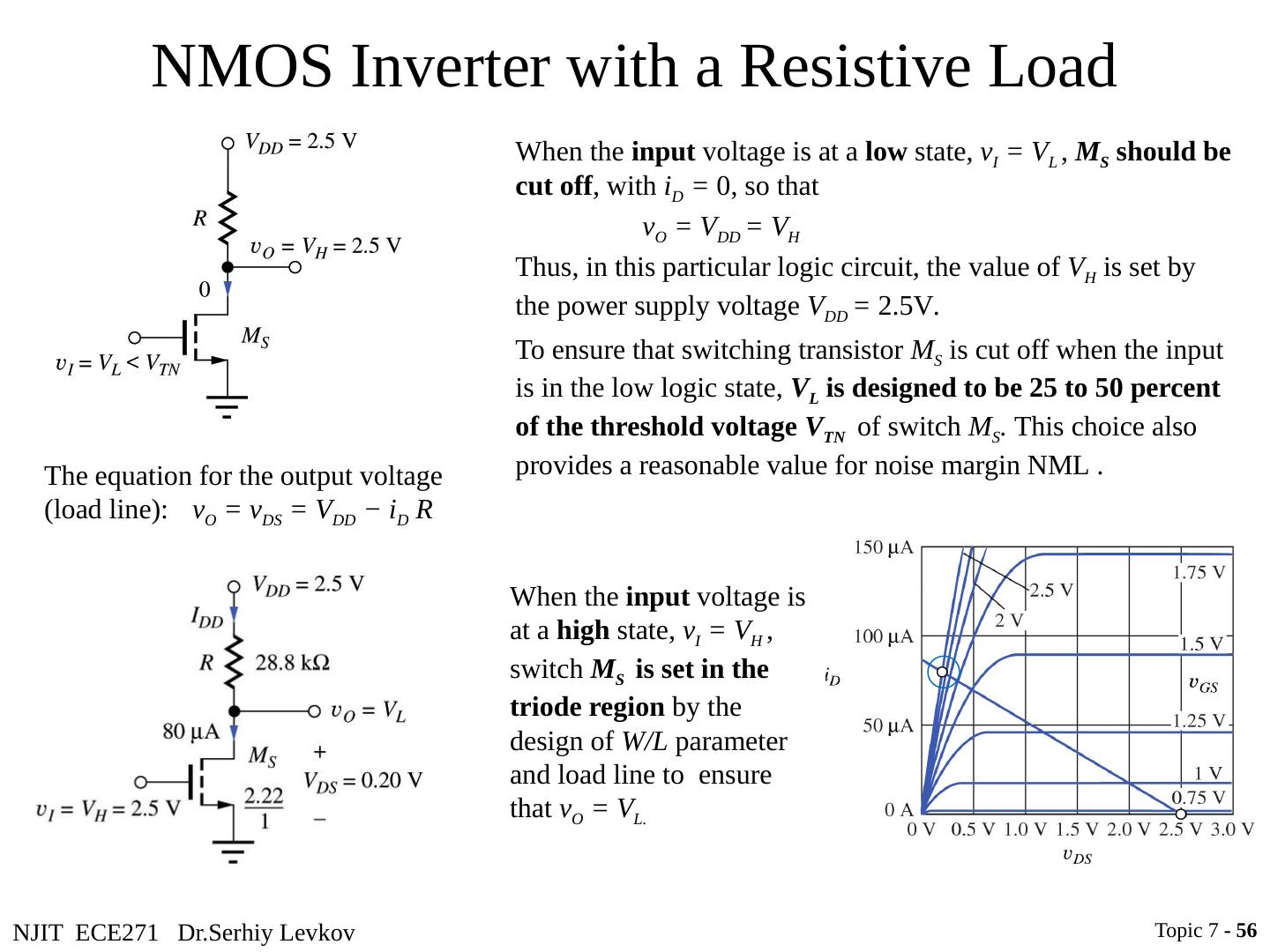
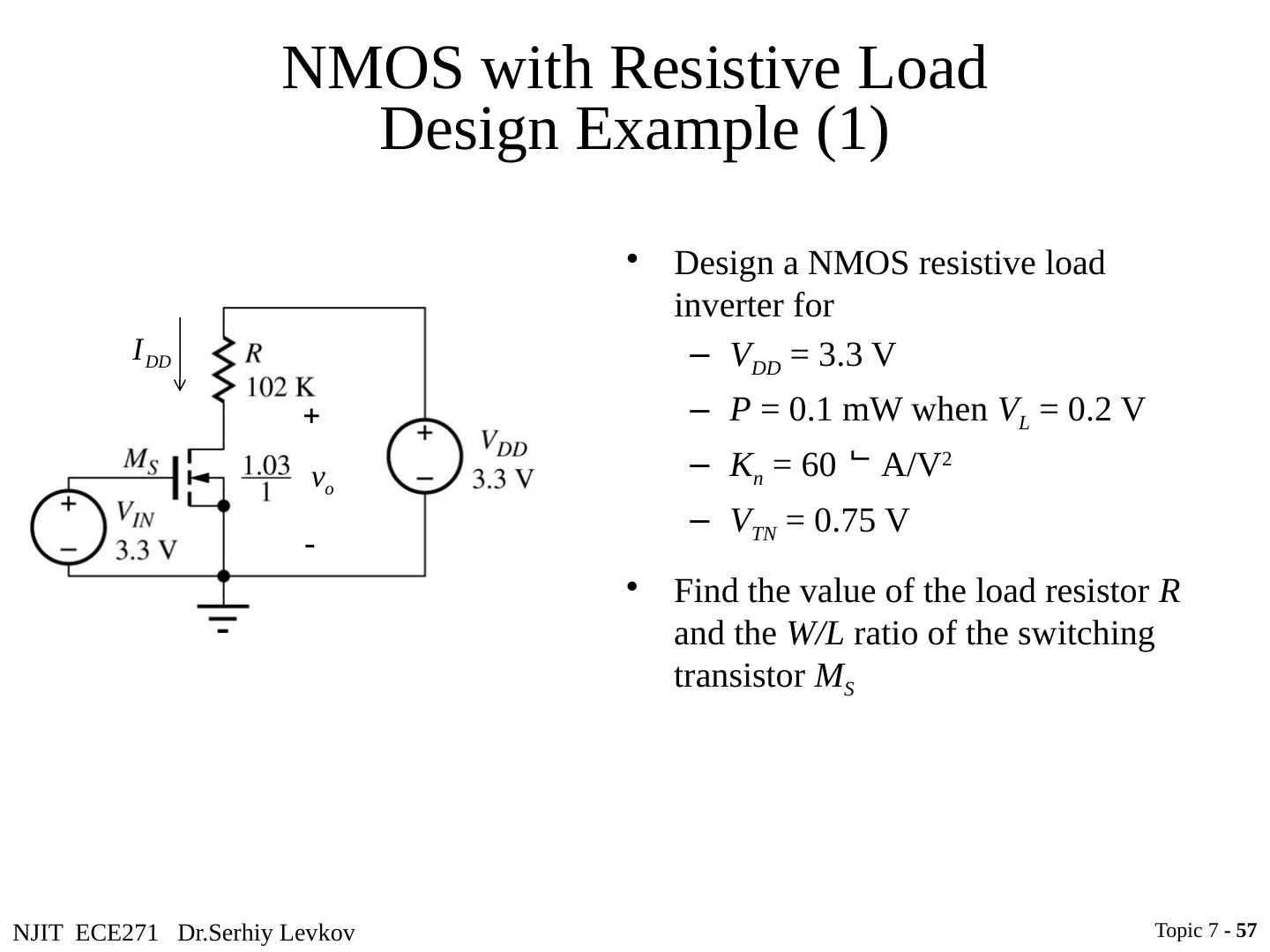
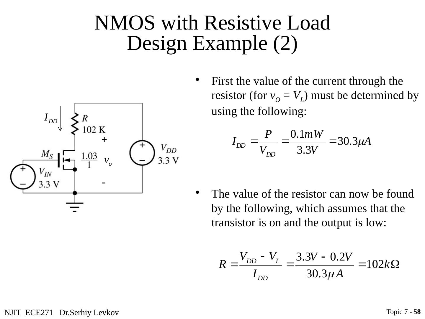
用数字电路介绍数字电子学
展开查看详情
1 .NJIT ECE271 Dr.Serhiy Levkov Topic 7 - 1 Topic 7 Digital Circuits Intro to Digital Electronics ECE 271 Electronic Circuits I
2 .NJIT ECE271 Dr.Serhiy Levkov Brief History of Digital Electronics Digital electronics can be found in many applications in the form of microprocessors, microcontrollers, PCs, DSPs, and an uncountable number of other systems. The historic development of design of digital circuits: resistor-transistor logic (RTL) diode-transistor logic (DTL) transistor-transistor logic (TTL) emitter-coupled logic (ECL) NMOS complementary MOS (CMOS) Topic 7 - 2
3 .NJIT ECE271 Dr.Serhiy Levkov Digital Binary Logic Digital electronics represent signals by discrete bands of analog levels, rather than by a continuous range. Topic 7 - 3
4 .NJIT ECE271 Dr.Serhiy Levkov Digital Binary Logic Digital electronics represent signals by discrete bands of analog levels, rather than by a continuous range. All levels within a band represent the same signal state. Small changes to the analog signal levels due to manufacturing tolerance, or noise do not leave the discrete envelope, and as a result are ignored by signal state sensing circuitry. Topic 7 - 4
5 .NJIT ECE271 Dr.Serhiy Levkov Digital Binary Logic Digital electronics represent signals by discrete bands of analog levels, rather than by a continuous range. All levels within a band represent the same signal state. Small changes to the analog signal levels due to manufacturing tolerance, or noise do not leave the discrete envelope, and as a result are ignored by signal state sensing circuitry. Binary logic is the most common style of digital logic. The signal is either a 0 (low, false) or a 1 (high, true) - Positive Logic Convention Topic 7 - 5
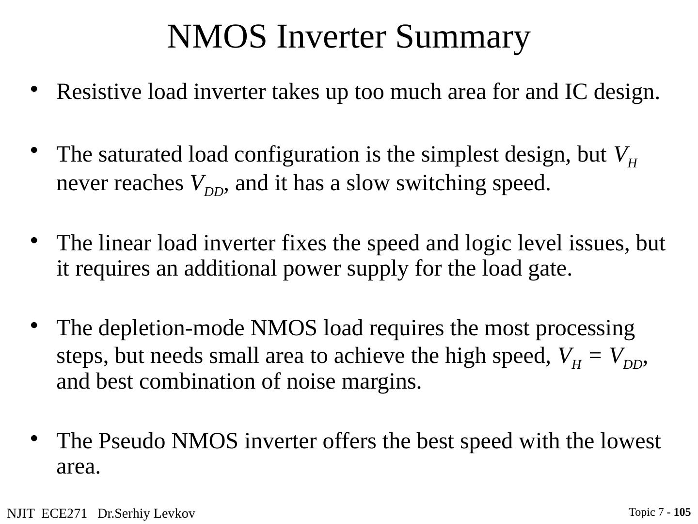
6 .NJIT ECE271 Dr.Serhiy Levkov Digital Binary Logic Digital electronics represent signals by discrete bands of analog levels, rather than by a continuous range. All levels within a band represent the same signal state. Small changes to the analog signal levels due to manufacturing tolerance, or noise do not leave the discrete envelope, and as a result are ignored by signal state sensing circuitry. Binary logic is the most common style of digital logic. The signal is either a 0 (low, false) or a 1 (high, true) - Positive Logic Convention Mathematical representation of logical operations is Boolean algebra: set of operations (NOT, AND, OR, NAND, NOR, etc.) with binary or logical elements. To perform general logical operations, a logic family must contain NOT and at least one another function of two inputs OR or AND. Topic 7 - 6
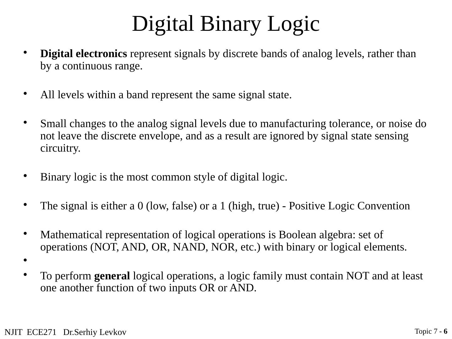
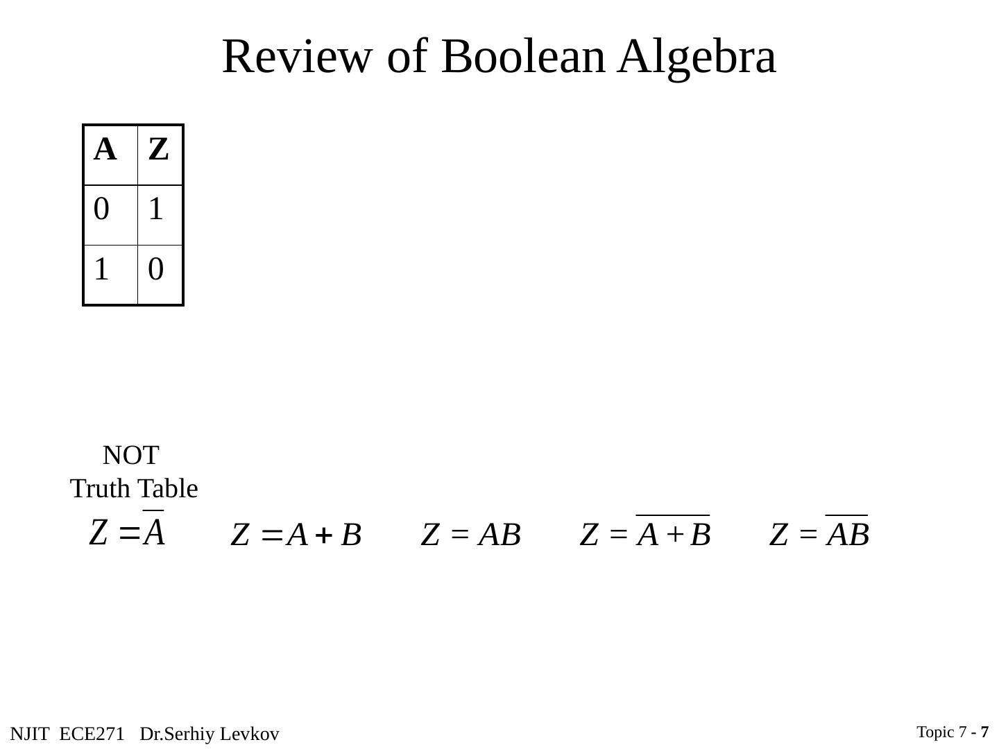
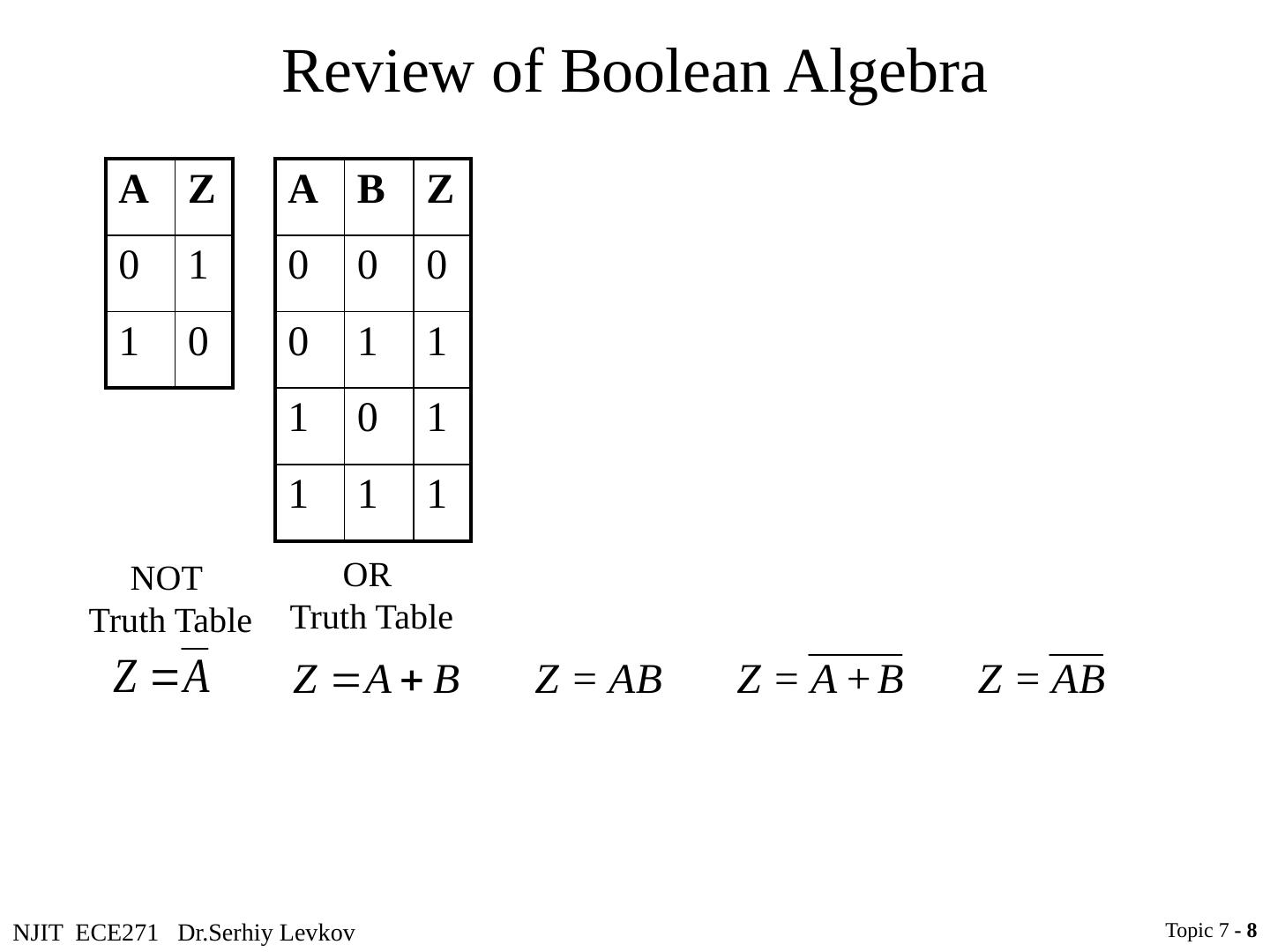
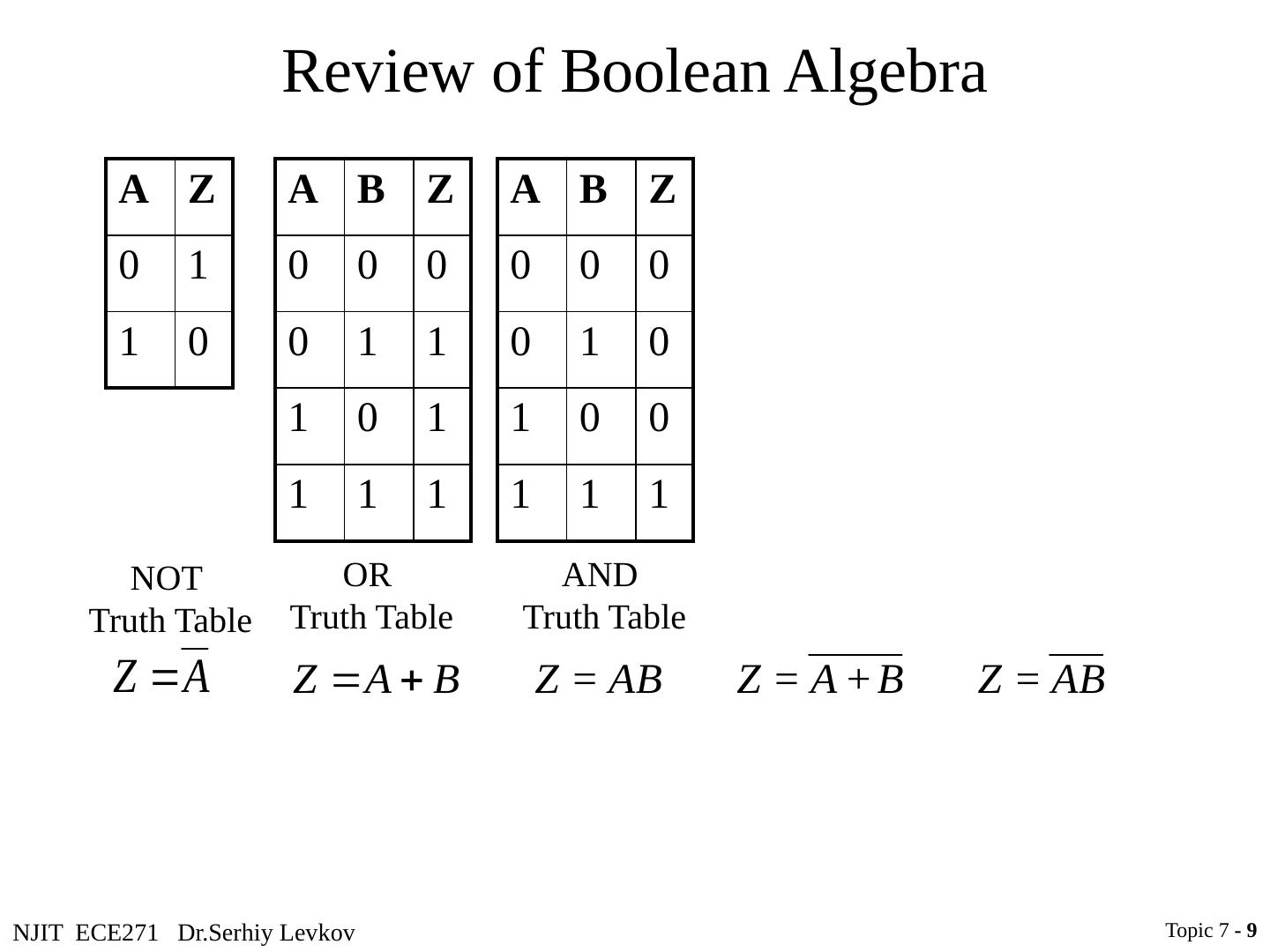
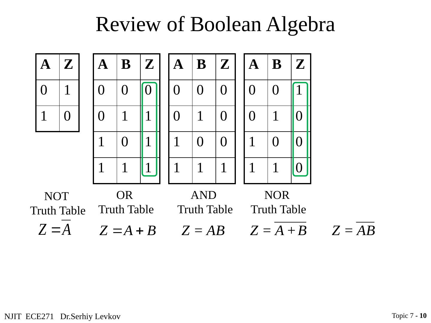
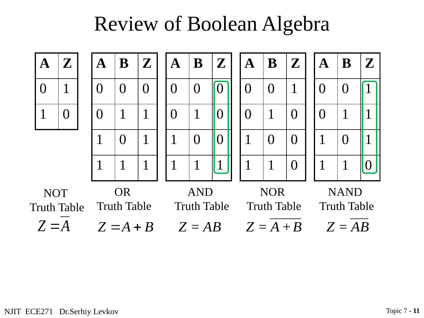
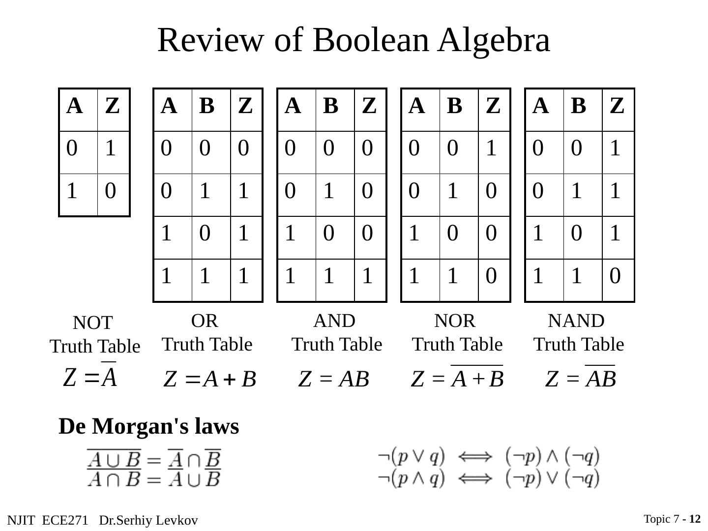
7 .NJIT ECE271 Dr.Serhiy Levkov Review of Boolean Algebra A Z 0 1 1 0 A B Z 0 0 0 0 1 1 1 0 1 1 1 1 A B Z 0 0 0 0 1 0 1 0 0 1 1 1 NOT Truth Table OR Truth Table AND Truth Table A B Z 0 0 1 0 1 0 1 0 0 1 1 0 A B Z 0 0 1 0 1 1 1 0 1 1 1 0 NOR Truth Table NAND Truth Table Topic 7 - 7
8 .NJIT ECE271 Dr.Serhiy Levkov Review of Boolean Algebra A Z 0 1 1 0 A B Z 0 0 0 0 1 1 1 0 1 1 1 1 A B Z 0 0 0 0 1 0 1 0 0 1 1 1 NOT Truth Table OR Truth Table AND Truth Table A B Z 0 0 1 0 1 0 1 0 0 1 1 0 A B Z 0 0 1 0 1 1 1 0 1 1 1 0 NOR Truth Table NAND Truth Table Topic 7 - 8
9 .NJIT ECE271 Dr.Serhiy Levkov Review of Boolean Algebra A Z 0 1 1 0 A B Z 0 0 0 0 1 1 1 0 1 1 1 1 A B Z 0 0 0 0 1 0 1 0 0 1 1 1 NOT Truth Table OR Truth Table AND Truth Table A B Z 0 0 1 0 1 0 1 0 0 1 1 0 A B Z 0 0 1 0 1 1 1 0 1 1 1 0 NOR Truth Table NAND Truth Table Topic 7 - 9
10 .NJIT ECE271 Dr.Serhiy Levkov Review of Boolean Algebra A Z 0 1 1 0 A B Z 0 0 0 0 1 1 1 0 1 1 1 1 A B Z 0 0 0 0 1 0 1 0 0 1 1 1 NOT Truth Table OR Truth Table AND Truth Table A B Z 0 0 1 0 1 0 1 0 0 1 1 0 A B Z 0 0 1 0 1 1 1 0 1 1 1 0 NOR Truth Table NAND Truth Table Topic 7 - 10
11 .NJIT ECE271 Dr.Serhiy Levkov Review of Boolean Algebra A Z 0 1 1 0 A B Z 0 0 0 0 1 1 1 0 1 1 1 1 A B Z 0 0 0 0 1 0 1 0 0 1 1 1 NOT Truth Table OR Truth Table AND Truth Table A B Z 0 0 1 0 1 0 1 0 0 1 1 0 A B Z 0 0 1 0 1 1 1 0 1 1 1 0 NOR Truth Table NAND Truth Table Topic 7 - 11
12 .NJIT ECE271 Dr.Serhiy Levkov Review of Boolean Algebra A Z 0 1 1 0 A B Z 0 0 0 0 1 1 1 0 1 1 1 1 A B Z 0 0 0 0 1 0 1 0 0 1 1 1 NOT Truth Table OR Truth Table AND Truth Table A B Z 0 0 1 0 1 0 1 0 0 1 1 0 A B Z 0 0 1 0 1 1 1 0 1 1 1 0 NOR Truth Table NAND Truth Table Topic 7 - 11
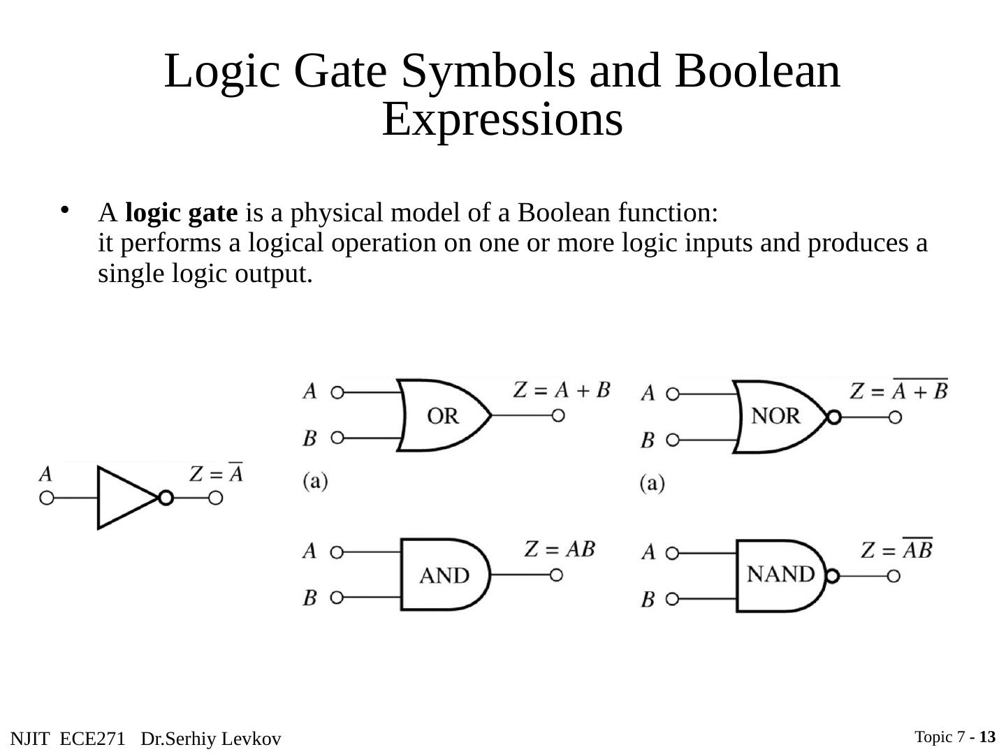
13 .NJIT ECE271 Dr.Serhiy Levkov Logic Gate Symbols and Boolean Expressions Topic 7 - 13 A logic gate is a physical model of a Boolean function: it performs a logical operation on one or more logic inputs and produces a single logic output.
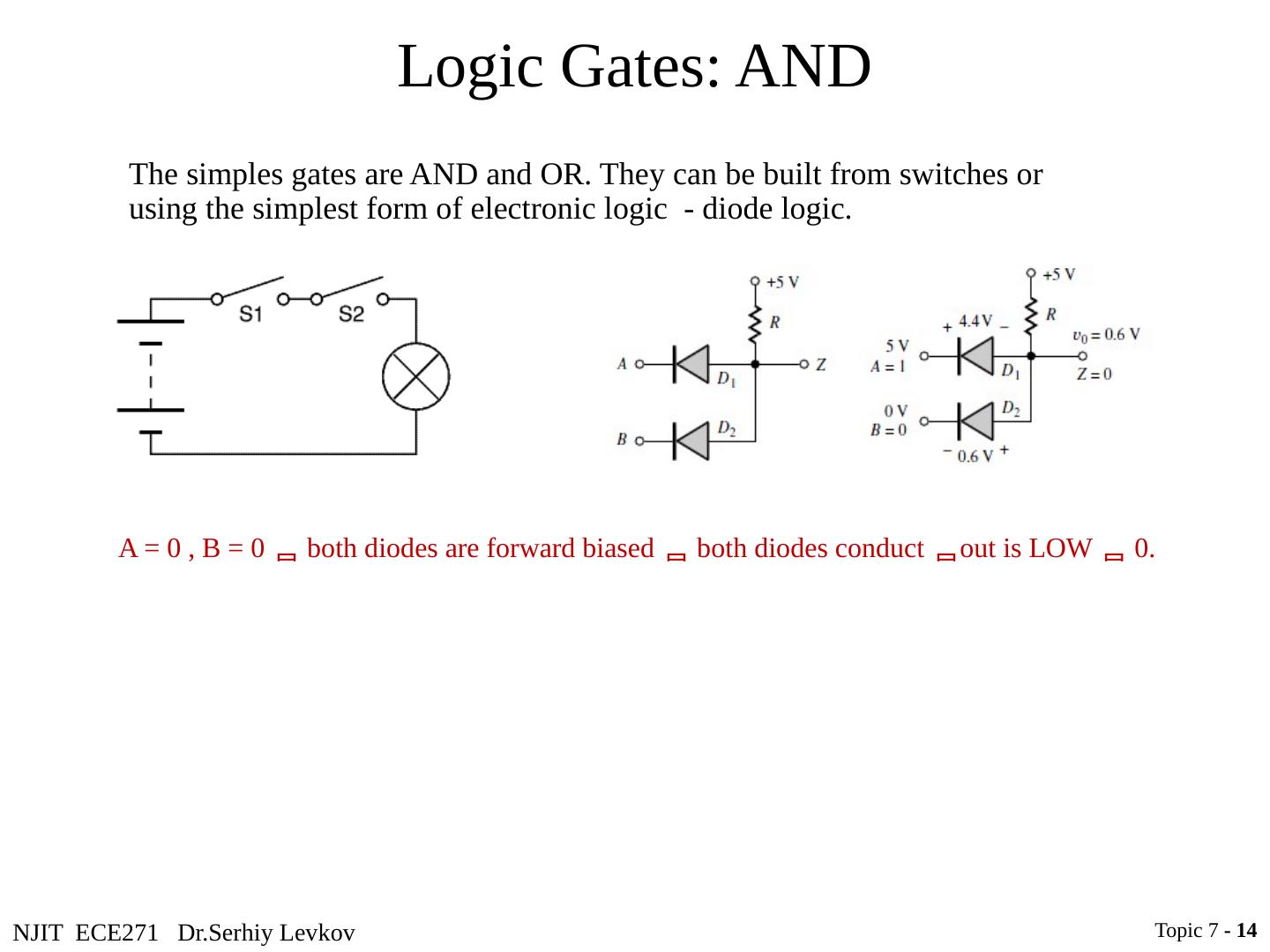
14 .NJIT ECE271 Dr.Serhiy Levkov Logic Gates: AND Topic 7 - 14 A = 0 , B = 0 both diodes are forward biased both diodes conduct out is LOW 0 . The simples gates are AND and OR. They can be built from switches or using the simplest form of electronic logic - diode logic.
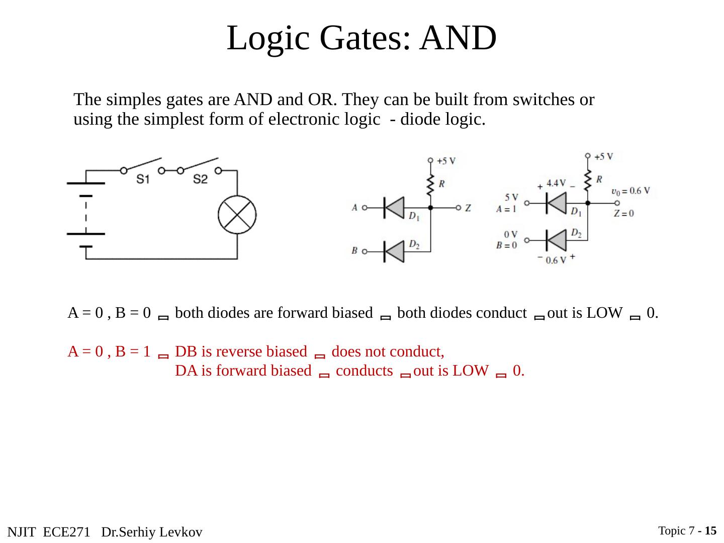
15 .NJIT ECE271 Dr.Serhiy Levkov Logic Gates: AND Topic 7 - 15 A = 0 , B = 0 both diodes are forward biased both diodes conduct out is LOW 0 . A = 0 , B = 1 DB is reverse biased does not conduct, DA is forward biased conducts out is LOW 0 . The simples gates are AND and OR. They can be built from switches or using the simplest form of electronic logic - diode logic.
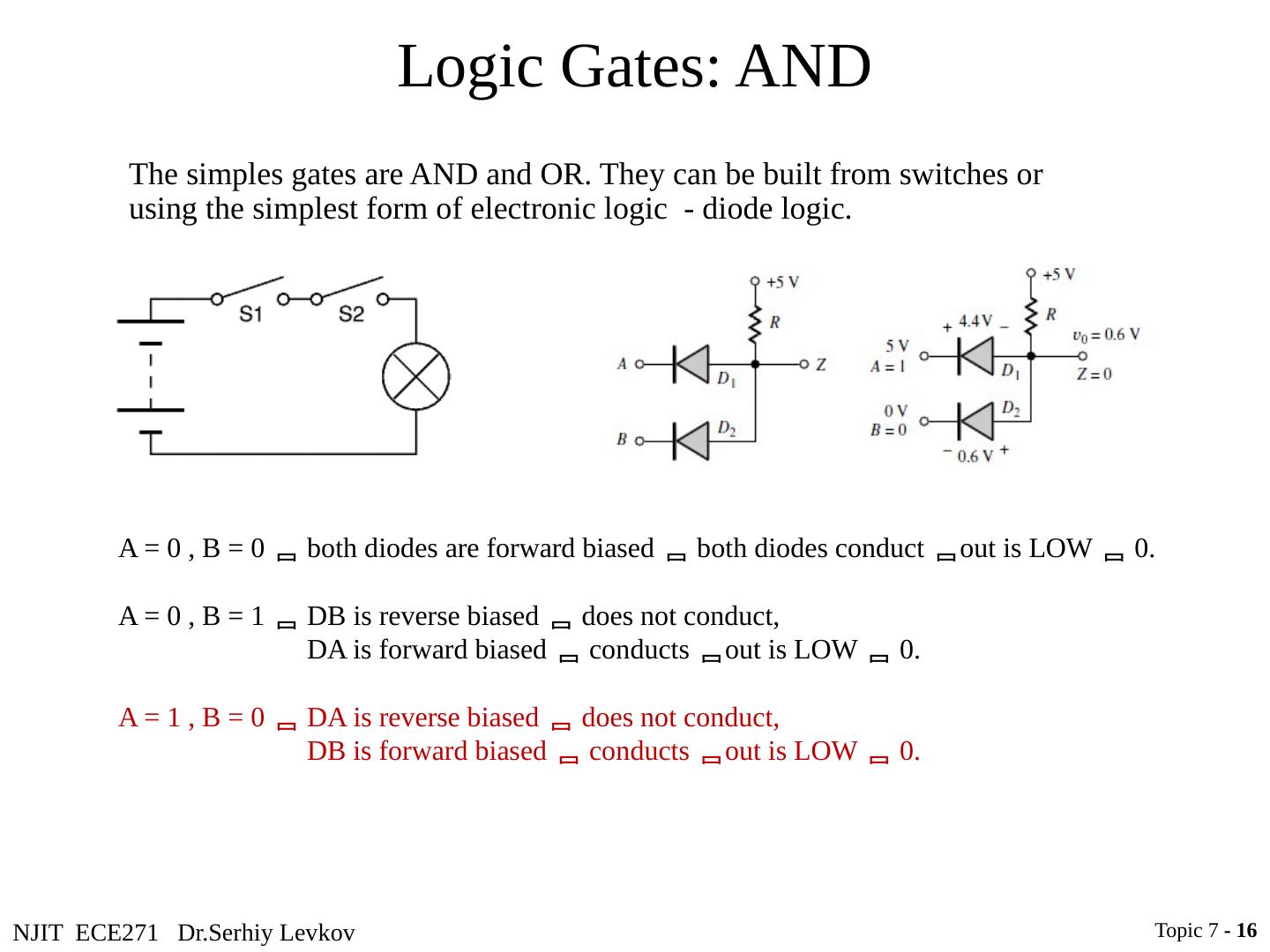
16 .NJIT ECE271 Dr.Serhiy Levkov Logic Gates: AND Topic 7 - 16 A = 0 , B = 0 both diodes are forward biased both diodes conduct out is LOW 0 . A = 0 , B = 1 DB is reverse biased does not conduct, DA is forward biased conducts out is LOW 0 . A = 1 , B = 0 DA is reverse biased does not conduct, DB is forward biased conducts out is LOW 0 . The simples gates are AND and OR. They can be built from switches or using the simplest form of electronic logic - diode logic.
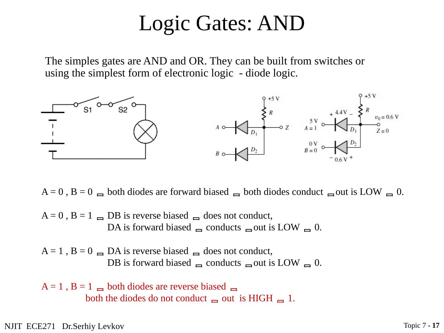
17 .NJIT ECE271 Dr.Serhiy Levkov Logic Gates: AND Topic 7 - 17 A = 0 , B = 0 both diodes are forward biased both diodes conduct out is LOW 0 . A = 0 , B = 1 DB is reverse biased does not conduct, DA is forward biased conducts out is LOW 0 . A = 1 , B = 0 DA is reverse biased does not conduct, DB is forward biased conducts out is LOW 0 . A = 1 , B = 1 both diodes are reverse biased both the diodes do not conduct out is HIGH 1 . The simples gates are AND and OR. They can be built from switches or using the simplest form of electronic logic - diode logic.
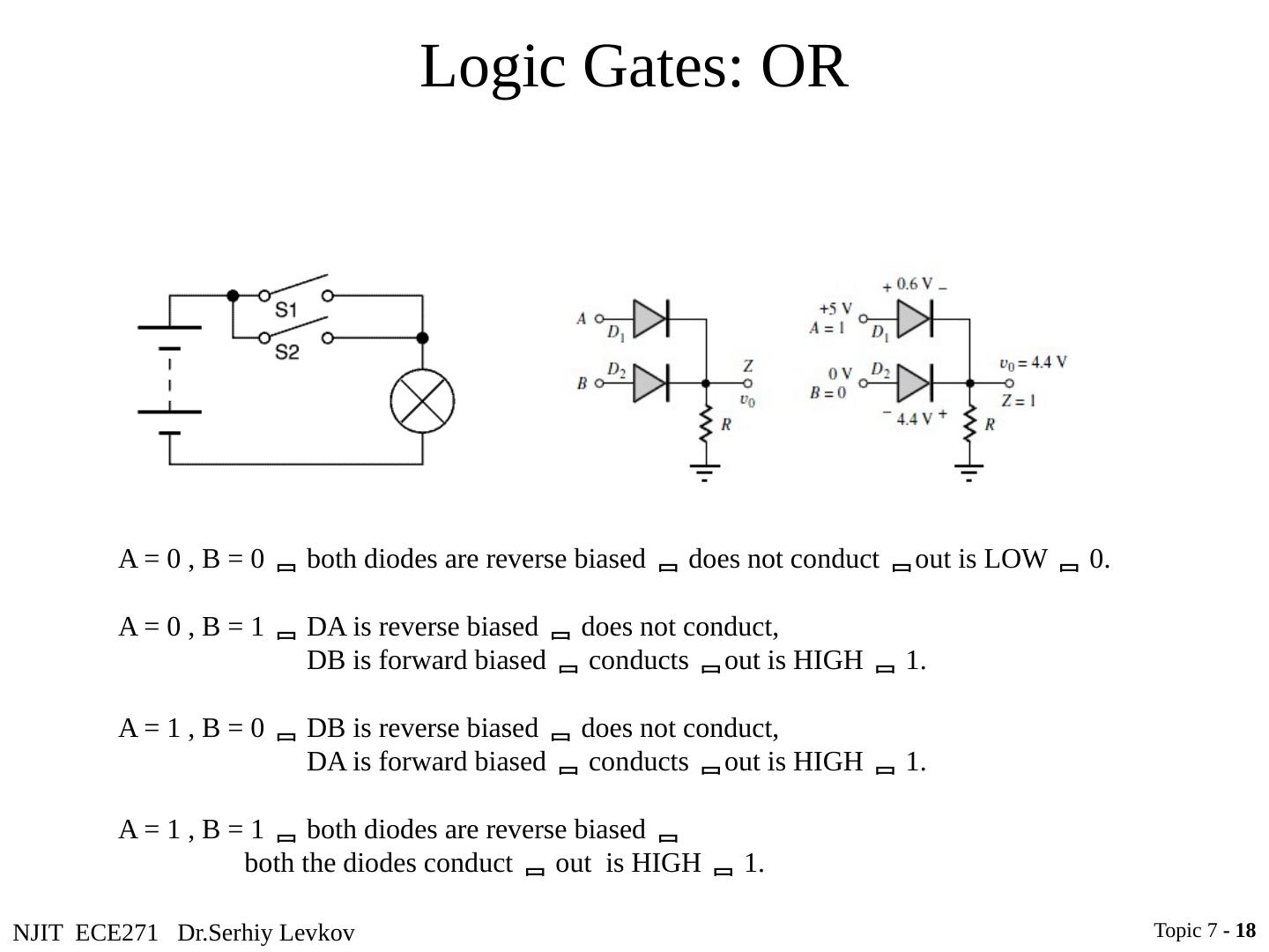
18 .NJIT ECE271 Dr.Serhiy Levkov Logic Gates: OR Topic 7 - 18 A = 0 , B = 0 both diodes are reverse biased does not conduct out is LOW 0 . A = 0 , B = 1 DA is reverse biased does not conduct, DB is forward biased conducts out is HIGH 1 . A = 1 , B = 0 DB is reverse biased does not conduct, DA is forward biased conducts out is HIGH 1 . A = 1 , B = 1 both diodes are reverse biased both the diodes conduct out is HIGH 1 .
19 .NJIT ECE271 Dr.Serhiy Levkov Logic Gates: NAND & NOR The simple diode logic allows AND and OR, but not inverters an incomplete form of logic. Also, without some kind of amplification it is not possible to have such basic logic operations cascaded as required for more complex logic functions. Topic 7 - 19
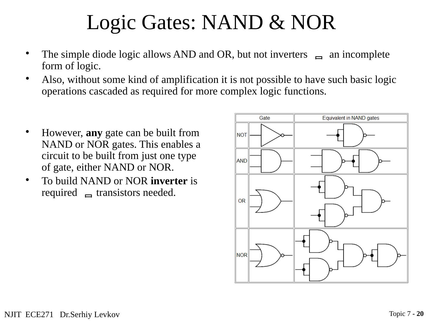
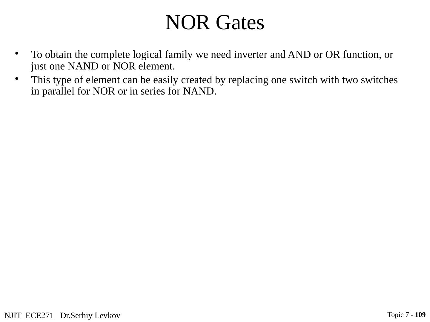
20 .NJIT ECE271 Dr.Serhiy Levkov Logic Gates: NAND & NOR The simple diode logic allows AND and OR, but not inverters an incomplete form of logic. Also, without some kind of amplification it is not possible to have such basic logic operations cascaded as required for more complex logic functions. Topic 7 - 20 However, any gate can be built from NAND or NOR gates. This enables a circuit to be built from just one type of gate, either NAND or NOR. To build NAND or NOR inverter is required transistors needed .
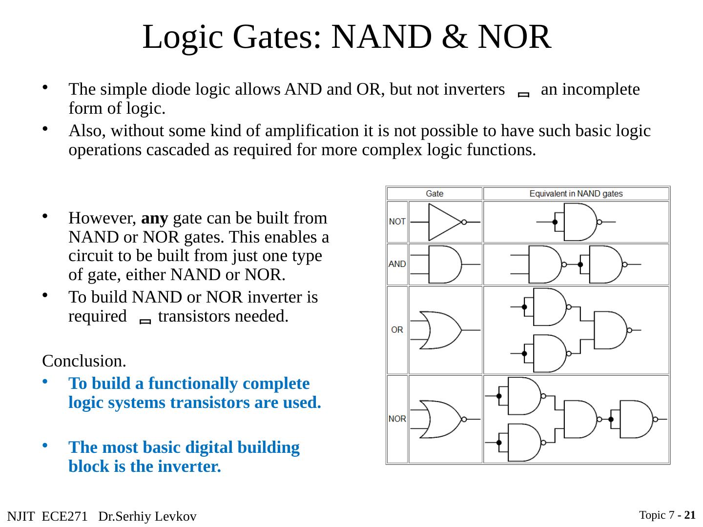
21 .NJIT ECE271 Dr.Serhiy Levkov Logic Gates: NAND & NOR The simple diode logic allows AND and OR, but not inverters an incomplete form of logic. Also, without some kind of amplification it is not possible to have such basic logic operations cascaded as required for more complex logic functions. Topic 7 - 21 However, any gate can be built from NAND or NOR gates. This enables a circuit to be built from just one type of gate, either NAND or NOR. To build NAND or NOR inverter is required transistors needed . Conclusion. To build a functionally complete logic systems transistors are used. The most basic digital building block is the inverter.
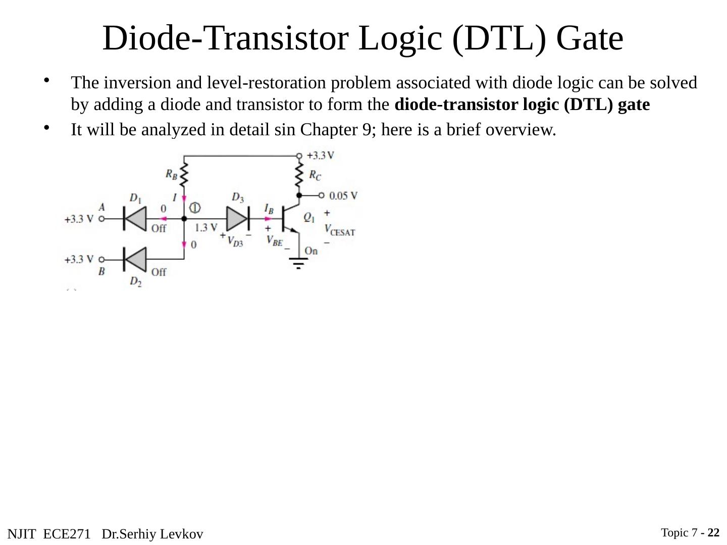
22 .NJIT ECE271 Dr.Serhiy Levkov Diode-Transistor Logic (DTL) Gate The inversion and level-restoration problem associated with diode logic can be solved by adding a diode and transistor to form the diode-transistor logic (DTL) gate It will be analyzed in detail sin Chapter 9; here is a brief overview. Topic 7 - 22
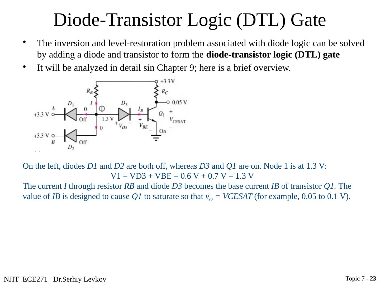
23 .NJIT ECE271 Dr.Serhiy Levkov Diode-Transistor Logic (DTL) Gate Topic 7 - 23 On the left, diodes D1 and D2 are both off, whereas D3 and Q1 are on. Node 1 is at 1.3 V: V1 = VD3 + VBE = 0.6 V + 0.7 V = 1.3 V The current I through resistor RB and diode D3 becomes the base current IB of transistor Q1. The value of IB is designed to cause Q1 to saturate so that v O = VCESAT (for example, 0.05 to 0.1 V). The inversion and level-restoration problem associated with diode logic can be solved by adding a diode and transistor to form the diode-transistor logic (DTL) gate It will be analyzed in detail sin Chapter 9; here is a brief overview.
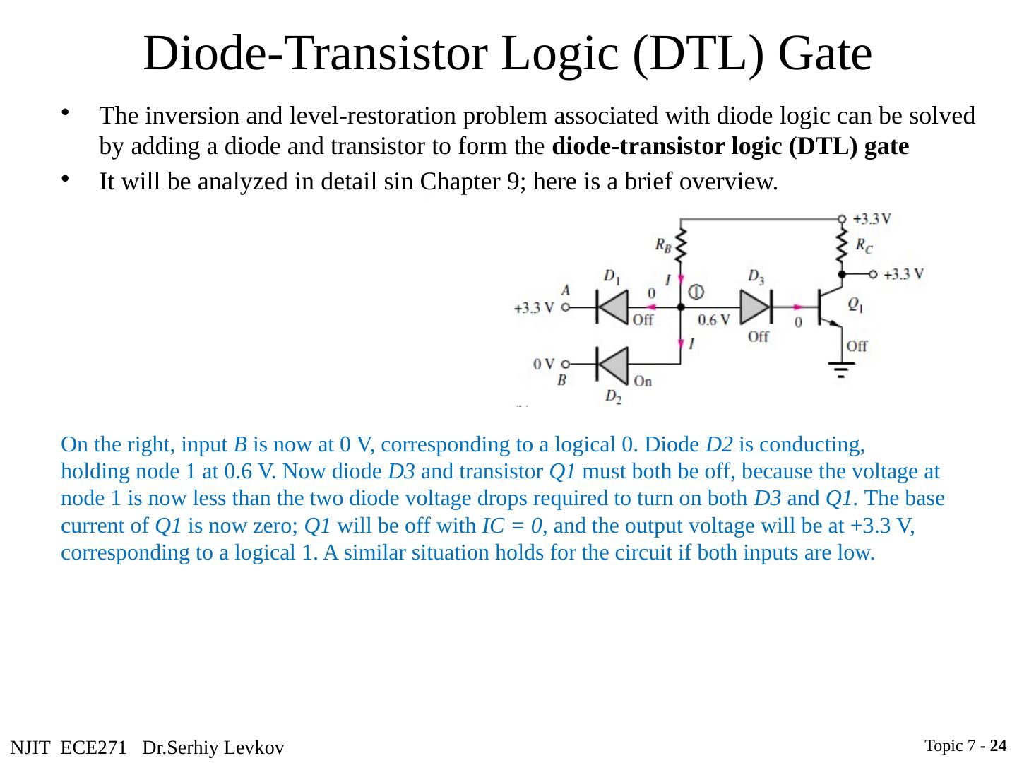
24 .NJIT ECE271 Dr.Serhiy Levkov Diode-Transistor Logic (DTL) Gate Topic 7 - 24 On the right, input B is now at 0 V, corresponding to a logical 0. Diode D2 is conducting, holding node 1 at 0.6 V. Now diode D3 and transistor Q1 must both be off, because the voltage at node 1 is now less than the two diode voltage drops required to turn on both D3 and Q1. The base current of Q1 is now zero; Q1 will be off with IC = 0, and the output voltage will be at +3.3 V, corresponding to a logical 1. A similar situation holds for the circuit if both inputs are low. The inversion and level-restoration problem associated with diode logic can be solved by adding a diode and transistor to form the diode-transistor logic (DTL) gate It will be analyzed in detail sin Chapter 9; here is a brief overview.
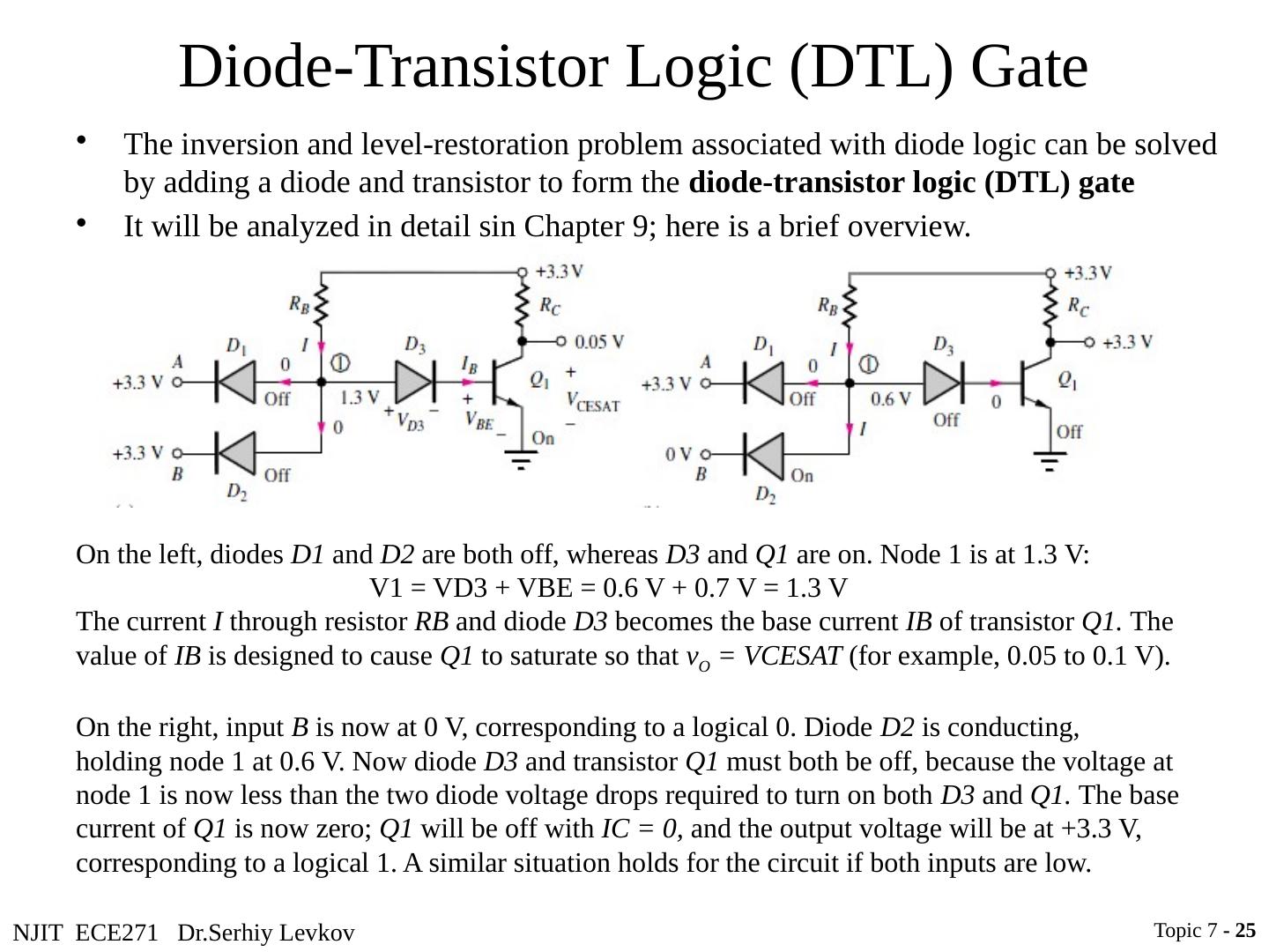
25 .NJIT ECE271 Dr.Serhiy Levkov Diode-Transistor Logic (DTL) Gate Topic 7 - 25 On the left, diodes D1 and D2 are both off, whereas D3 and Q1 are on. Node 1 is at 1.3 V: V1 = VD3 + VBE = 0.6 V + 0.7 V = 1.3 V The current I through resistor RB and diode D3 becomes the base current IB of transistor Q1. The value of IB is designed to cause Q1 to saturate so that v O = VCESAT (for example, 0.05 to 0.1 V). On the right, input B is now at 0 V, corresponding to a logical 0. Diode D2 is conducting, holding node 1 at 0.6 V. Now diode D3 and transistor Q1 must both be off, because the voltage at node 1 is now less than the two diode voltage drops required to turn on both D3 and Q1. The base current of Q1 is now zero; Q1 will be off with IC = 0, and the output voltage will be at +3.3 V, corresponding to a logical 1. A similar situation holds for the circuit if both inputs are low. The inversion and level-restoration problem associated with diode logic can be solved by adding a diode and transistor to form the diode-transistor logic (DTL) gate It will be analyzed in detail sin Chapter 9; here is a brief overview.
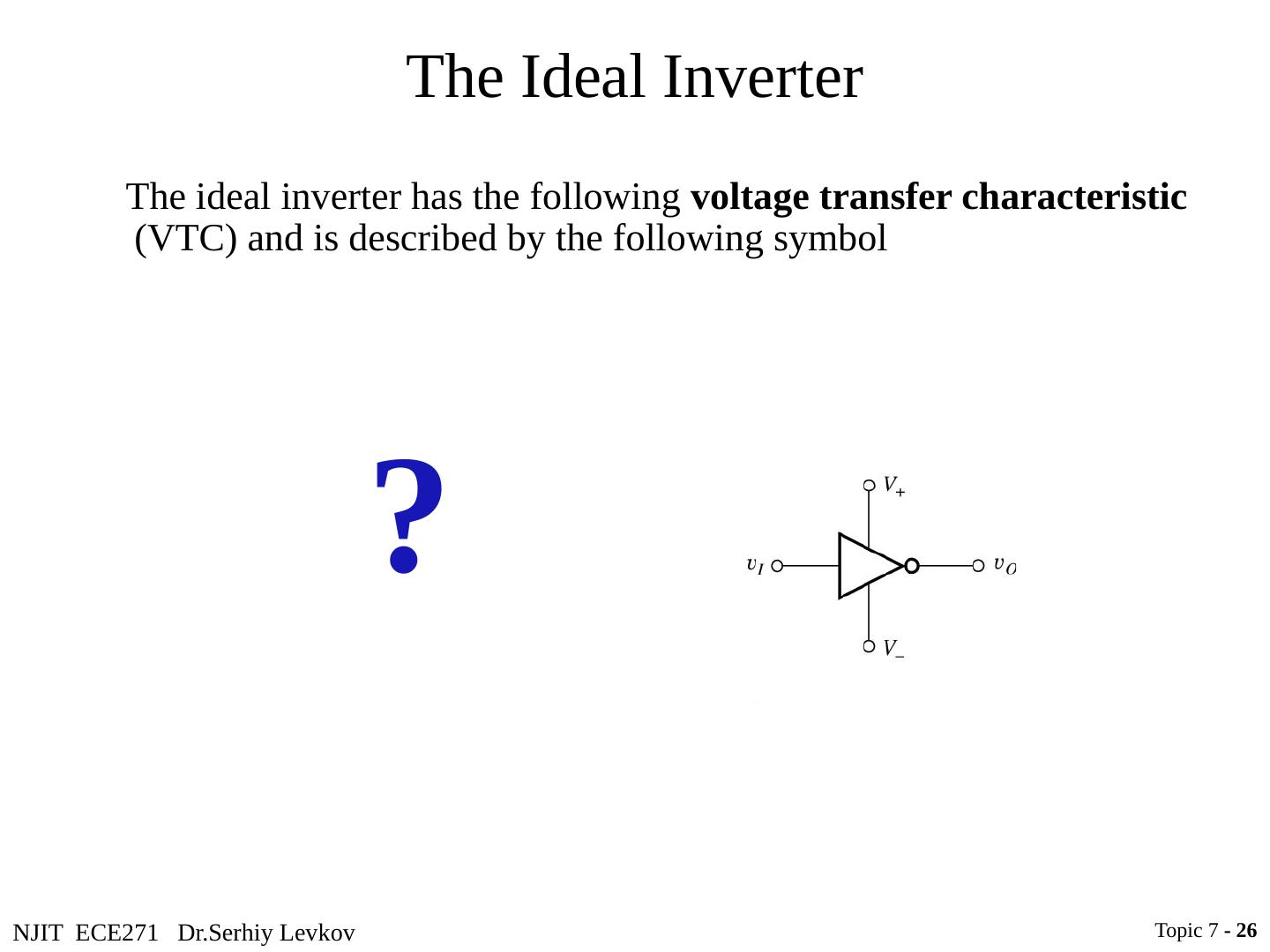
26 .NJIT ECE271 Dr.Serhiy Levkov The Ideal Inverter The ideal inverter has the following voltage transfer characteristic (VTC) and is described by the following symbol Topic 7 - 26 ?
27 .NJIT ECE271 Dr.Serhiy Levkov The Ideal Inverter The ideal inverter has the following voltage transfer characteristic (VTC) and is described by the following symbol V + and V - are the supply rails V H and V L describe the high and low logic levels at the output Topic 7 - 27
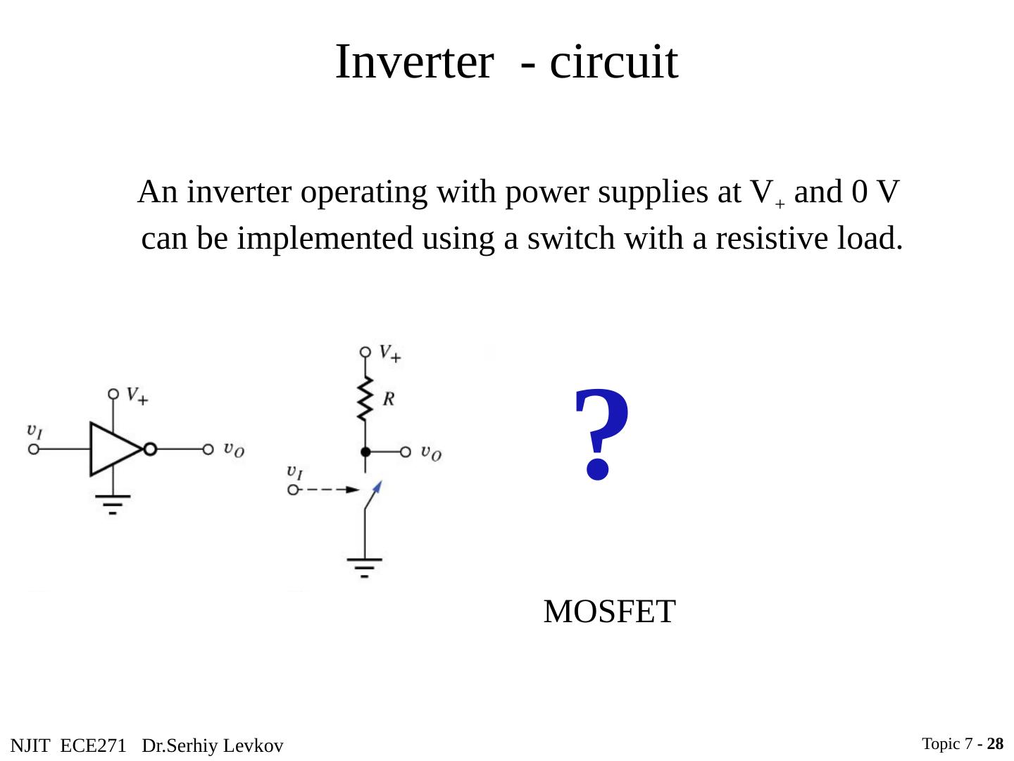
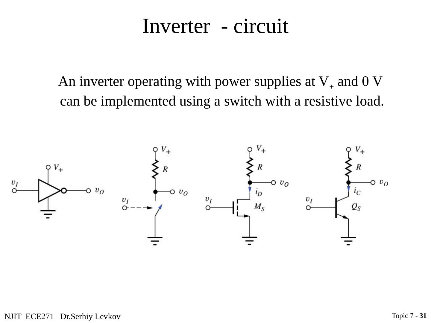
28 .NJIT ECE271 Dr.Serhiy Levkov Inverter - circuit An inverter operating with power supplies at V + and 0 V can be implemented using a switch with a resistive load. Topic 7 - 28 ? MOSFET
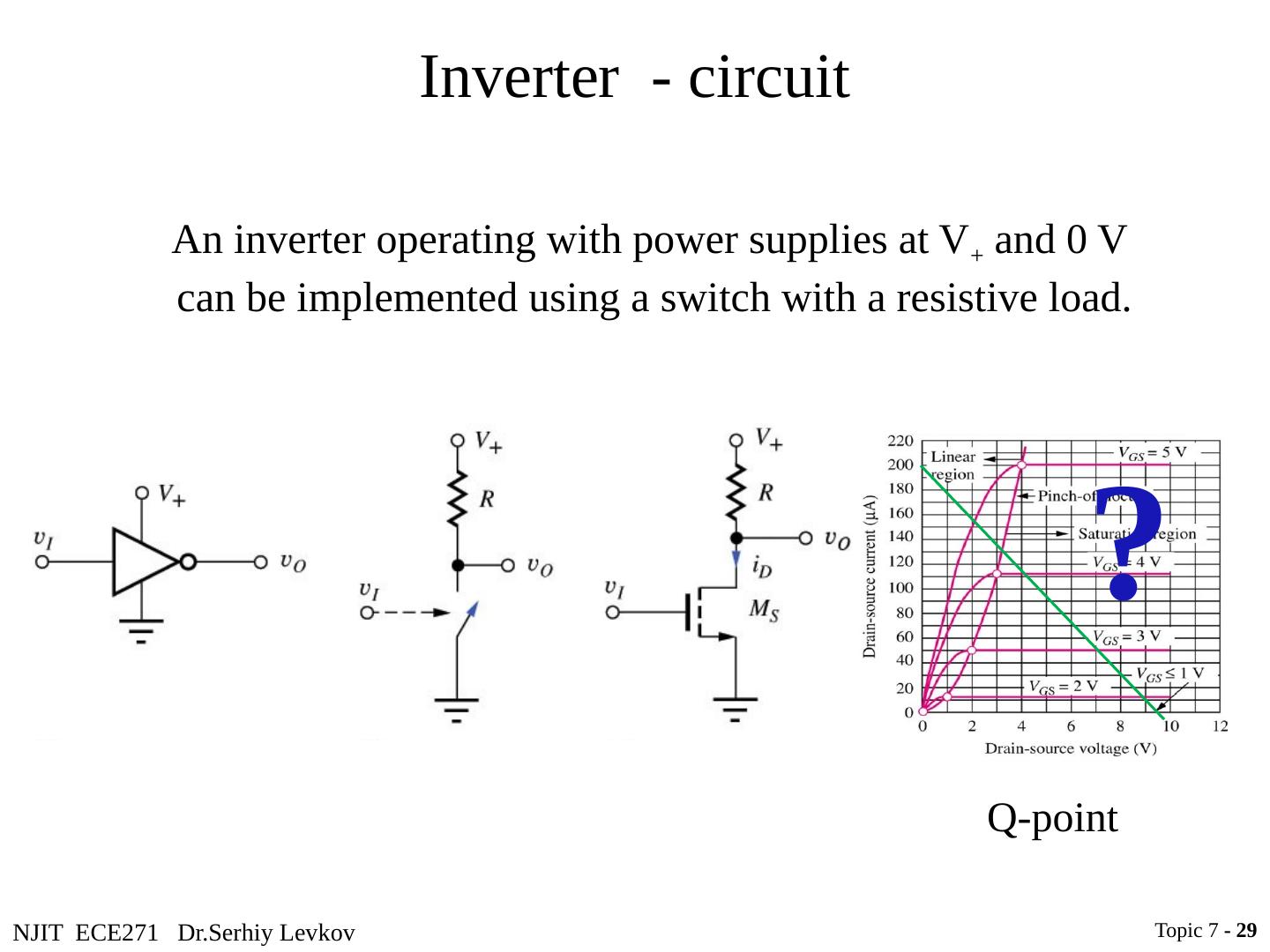
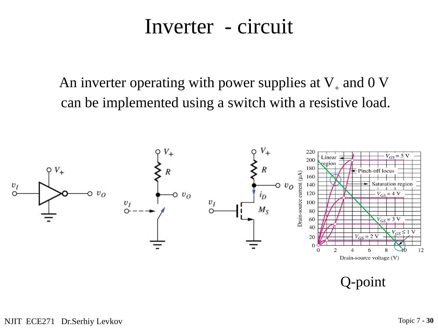
29 .NJIT ECE271 Dr.Serhiy Levkov Inverter - circuit An inverter operating with power supplies at V + and 0 V can be implemented using a switch with a resistive load. Topic 7 - 29 ? Q-point


