- 快召唤伙伴们来围观吧
- 微博 QQ QQ空间 贴吧
- 文档嵌入链接
- <iframe src="https://www.slidestalk.com/u214/Bipolar_Junction_Transistor?embed" frame border="0" width="640" height="360" scrolling="no" allowfullscreen="true">复制
- 微信扫一扫分享
双极结型晶体管(BJT)
展开查看详情
1 .Bipolar Junction Transistor ( BJT) Chapter 5
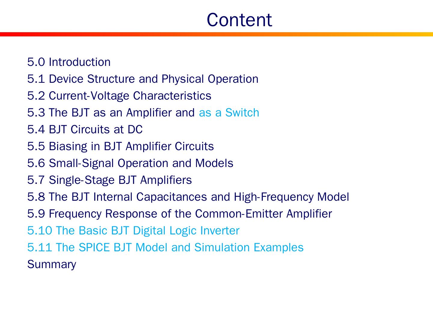
2 . Content 5.0 Introduction 5.1 Device Structure and Physical Operation 5.2 Current-Voltage Characteristics 5.3 The BJT as an Amplifier and as a Switch 5.4 BJT Circuits at DC 5.5 Biasing in BJT Amplifier Circuits 5.6 Small-Signal Operation and Models 5.7 Single-Stage BJT Amplifiers 5.8 The BJT Internal Capacitances and High-Frequency Model 5.9 Frequency Response of the Common-Emitter Amplifier 5.10 The Basic BJT Digital Logic Inverter 5.11 The SPICE BJT Model and Simulation Examples Summary
3 . Introduction Physical Structure Circuit Symbols for BJTs Modes of Operation Basic Characteristic
4 .5.1 Transistor Transistor is a three-terminal device, made of silicon (Germanium was early used) There are two types: NPN and PNP b) pn p transistor. a) npn transistor S implified structure
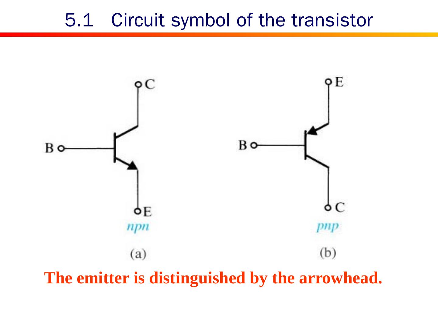
5 .5.1 Circuit symbol of the transistor The emitter is distinguished by the arrowhead.
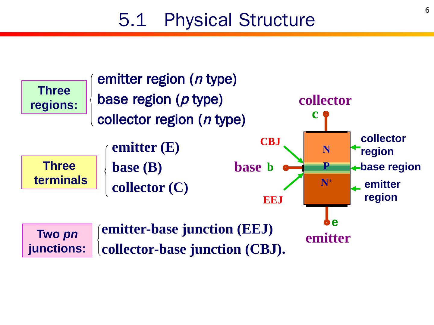
6 .5.1 Physical Structure emitter region ( n type) base region ( p type) collector region ( n type) emitter (E) base (B) collector (C) emitter-base junction (EEJ) collector-base junction (CBJ). Three regions: Three terminals Two pn junctions: EEJ CBJ emitter region base region collector region c collector b base emitter N P N + e 6
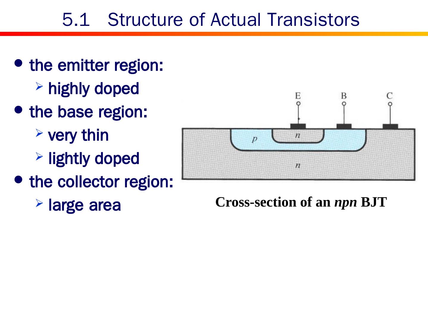
7 .5.1 Structure of Actual Transistors the emitter region: highly doped the base region: very thin lightly doped the collector region: large area Cross-section of an npn BJT +
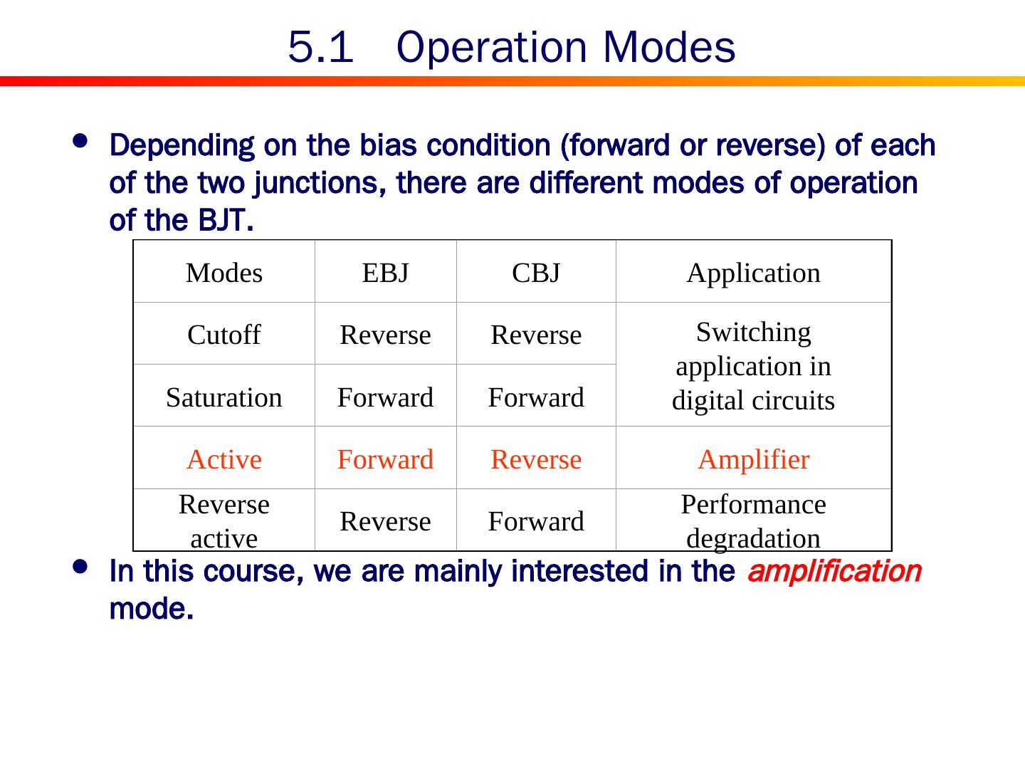
8 .5.1 Operation Modes Depending on the bias condition (forward or reverse) of each of the two junctions, there are different modes of operation of the BJT. In this course, we are mainly interested in the amplification mode. Modes EBJ CBJ Application Cutoff Reverse Reverse Switching application in digital circuits Saturation Forward Forward Active Forward Reverse Amplifier Reverse active Reverse Forward Performance degradation
9 .5.1 Transistor and Its Functionality A transistor can be used to realize a controlled current source . In the extreme, the current in the third terminal can be changed from zero to a large value switch application. Bias in Amplification Mode EBJ is forwardly biased CBJ is reversely biased
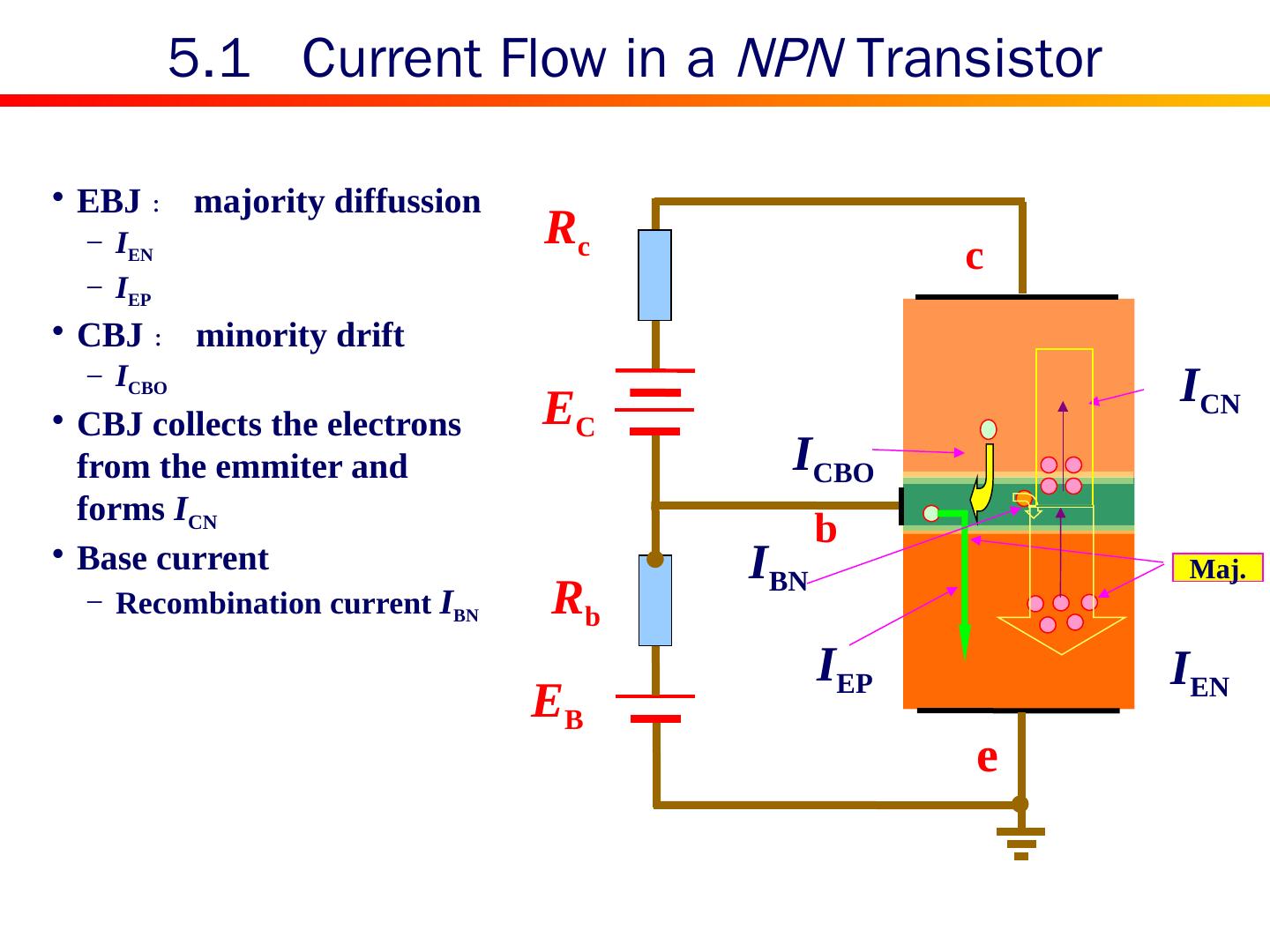
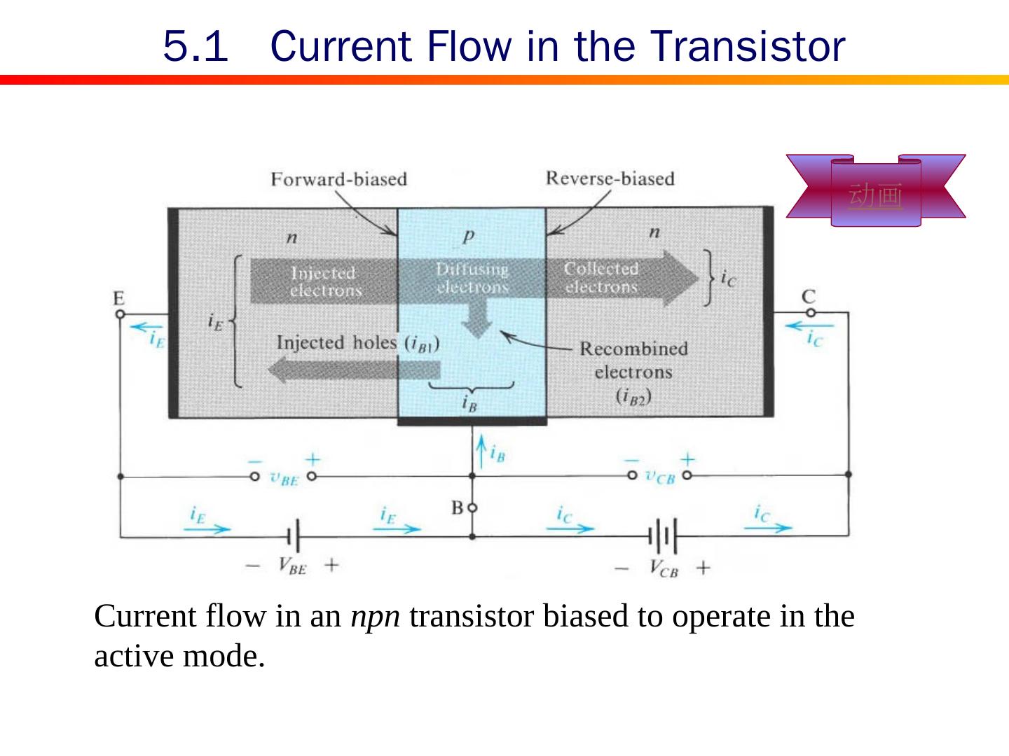
10 .R b R c E B E C e c b I EN I EP Maj. I CN I CBO I BN 5.1 Current Flow in a NPN Transistor EBJ : majority diffussion I EN I EP CBJ : minority drift I CBO CBJ collects the electrons from the emmiter and forms I CN Base current Recombination current I BN
11 .5.1 Practical Source Connection
12 .Current flow in an npn transistor biased to operate in the active mode. 5.1 Current Flow in the Transistor 动画
13 .5.2 Current Equation Terminal current relationship c b e i E i C i B i E = i B + i C
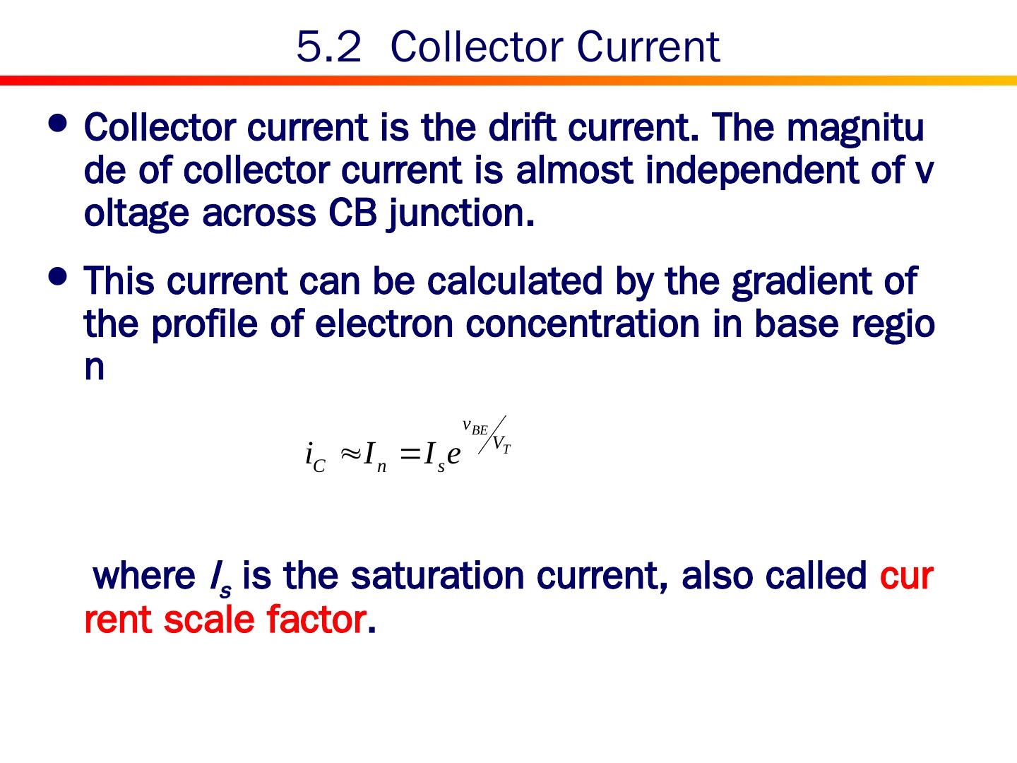
14 .5.2 Collector Current Collector current is the drift current. The magnitude of collector current is almost independent of voltage across CB junction. This current can be calculated by the gradient of the profile of electron concentration in base region where I s is the saturation current, also called current scale factor .
15 .5.2 Saturation Current Expression for saturation current: The saturation current is a strong function with temperature due to intrinsic carrier concentration. Its value is usually in the range of 10 -12 A to 10 -18 A.
16 .5.2 Base Current Base current consists of two components. Diffusion current Recombination current Recombination current is dominant. The value of base current is very small.
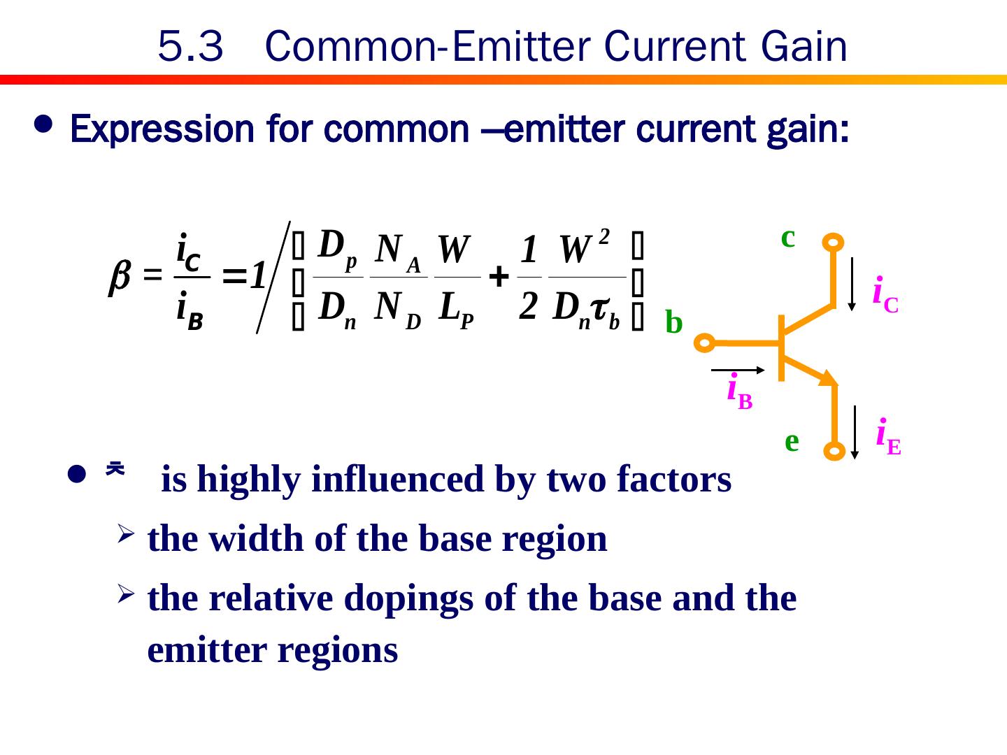
17 .5.3 Common-Emitter Current Gain Expression for common –emitter current gain: c b e i E i C i B is highly influenced by two factors the width of the base region the relative dopings of the base and the emitter regions
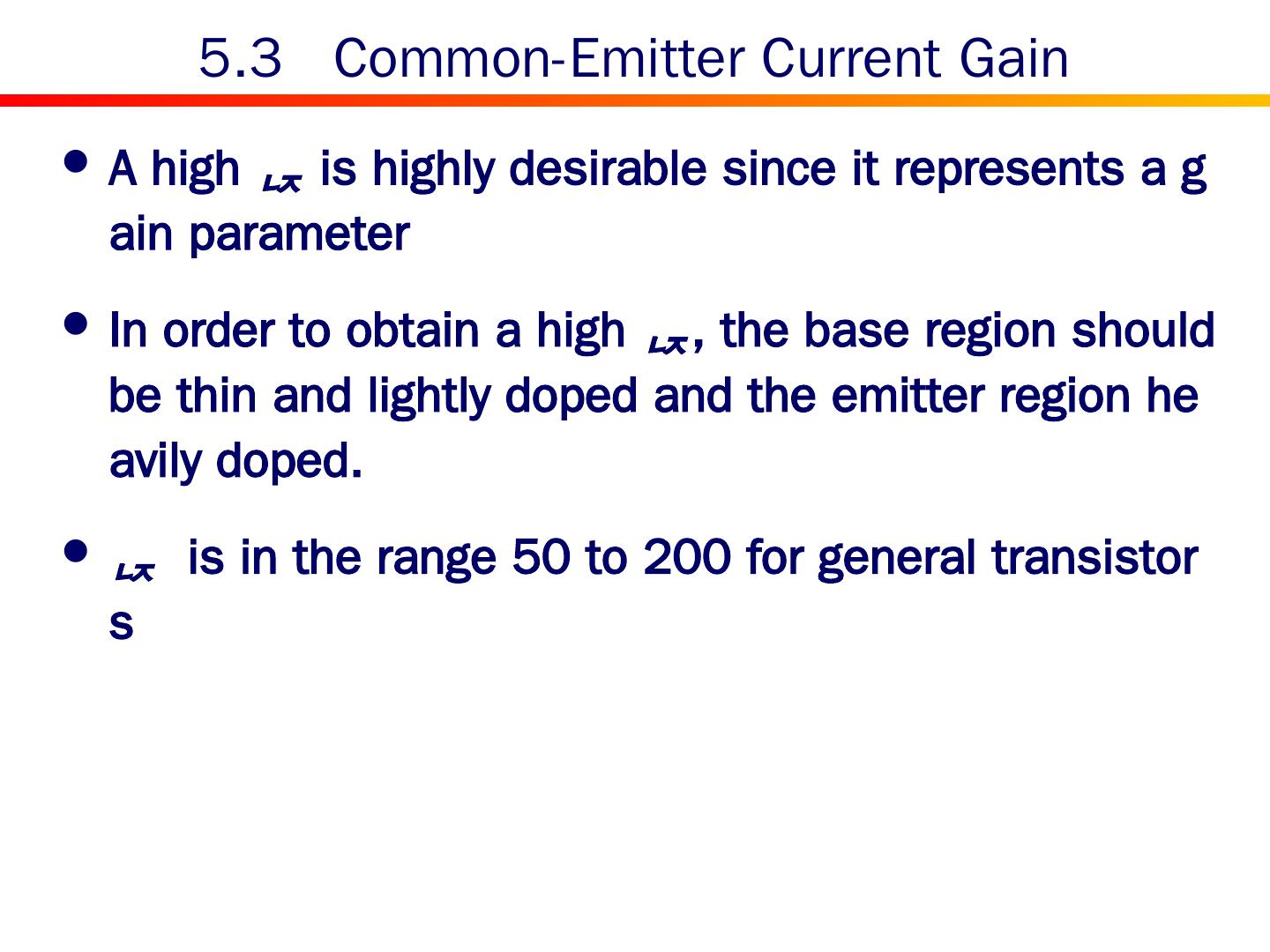
18 .5.3 Common-Emitter Current Gain A high is highly desirable since it represents a gain parameter In order to obtain a high , the base region should be thin and lightly doped and the emitter region heavily doped. is in the range 50 to 200 for general transistors
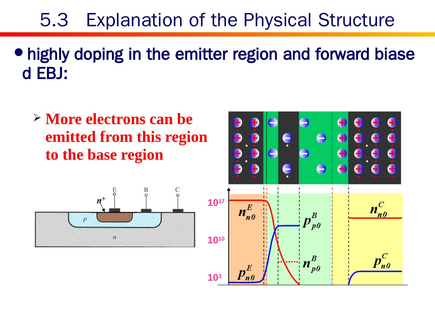
19 .highly doping in the emitter region and forward biased EBJ: 5.3 Explanation of the Physical Structure 10 17 10 10 10 3 More electrons can be emitted from this region to the base region
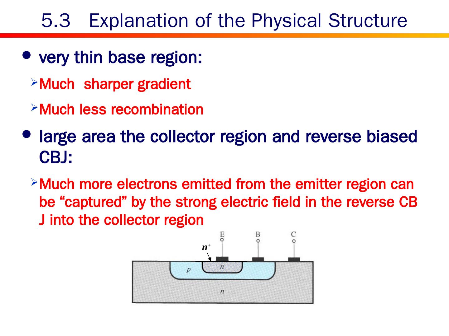
20 .very thin base region: Much sharper gradient Much less recombination large area the collector region and reverse biased CBJ: Much more electrons emitted from the emitter region can be “captured” by the strong electric field in the reverse CBJ into the collector region 5.3 Explanation of the Physical Structure n +
21 .5.3 CBJ and reversely biased diode The reversely biased CBJ behaves totally different from a reversely biased single diode, where almost no current flows. The huge difference arises from the minority concentration! In a BJT, the minority concentration in the Base region is extraordinarily high due to electrons injection from the Emitter region
22 .Expression for common-base current gain: Its value is less than but very close to unity. Small changes in α correspond to very large changes in β. 5.3 Common-Base Current Gain c b e i E i C i B
23 .5.3 Graphical representation The i C - v BE characteristic for an npn transistor
24 .5.3 Dependence of I C on V CE (b) The ideal i C – v CE characteristics (a) Conceptual circuit for measuring the i C – v CE characteristics of the BJT
25 .5.3 The Early Effect The i C – v CE characteristics of a practical BJT
26 .5.3 The Early Effect
27 .Large-signal Equivalent Circuit Models Analysis Steps Examples 5.4 Analysis of Transistor Circuit at DC
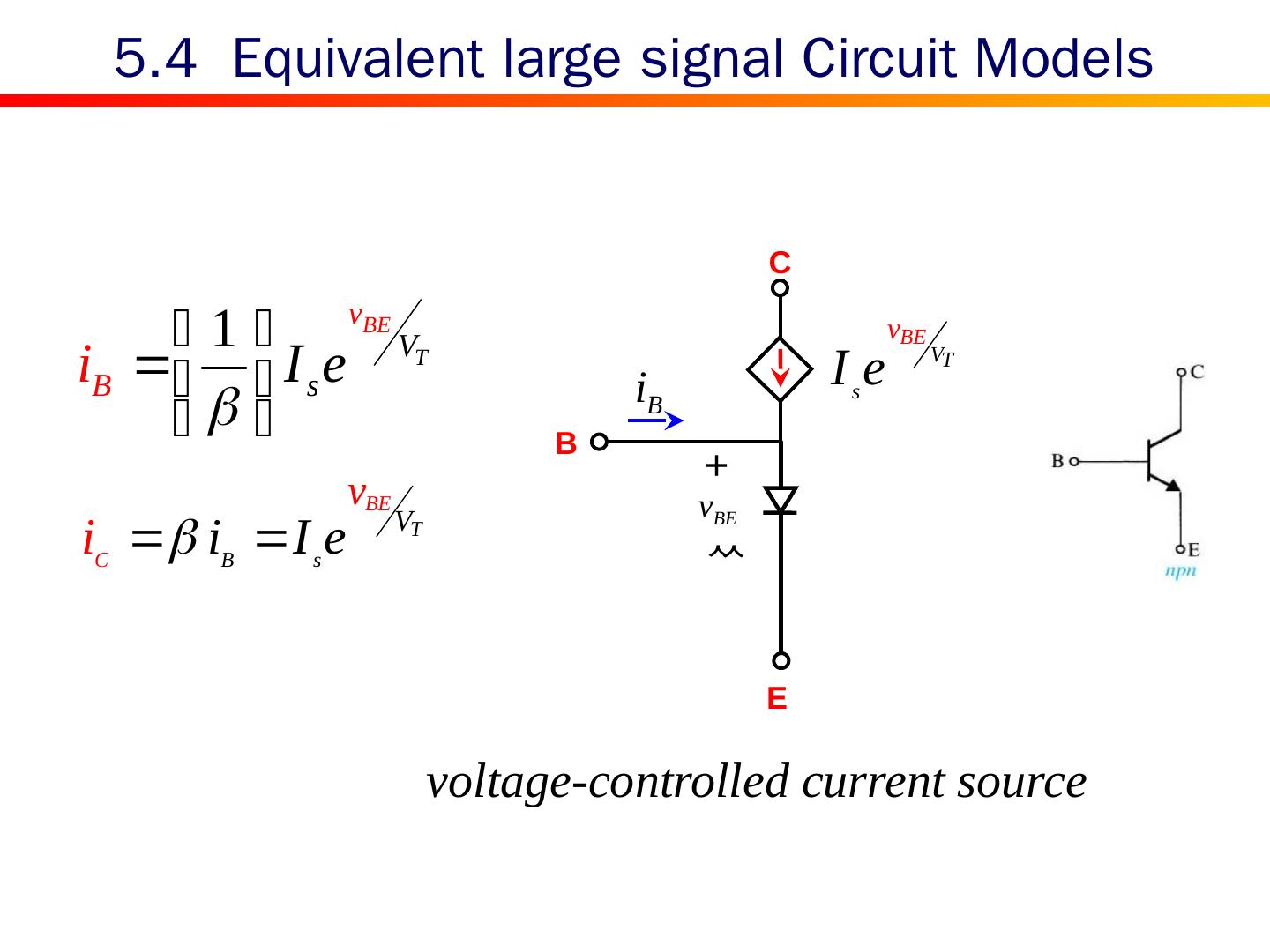
28 .5.4 Equivalent large signal Circuit Models voltage-controlled current source + B E C
29 .5.4 Equivalent large signal Circuit Models current-controlled current source No physical meaning Useful for DC analysis


