- 快召唤伙伴们来围观吧
- 微博 QQ QQ空间 贴吧
- 文档嵌入链接
- <iframe src="https://www.slidestalk.com/u214/Frequency_Response?embed" frame border="0" width="640" height="360" scrolling="no" allowfullscreen="true">复制
- 微信扫一扫分享
频率响应
展开查看详情
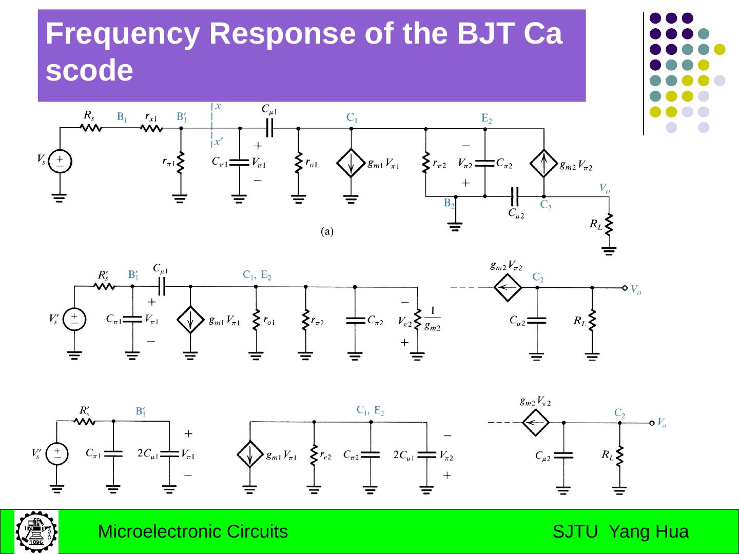
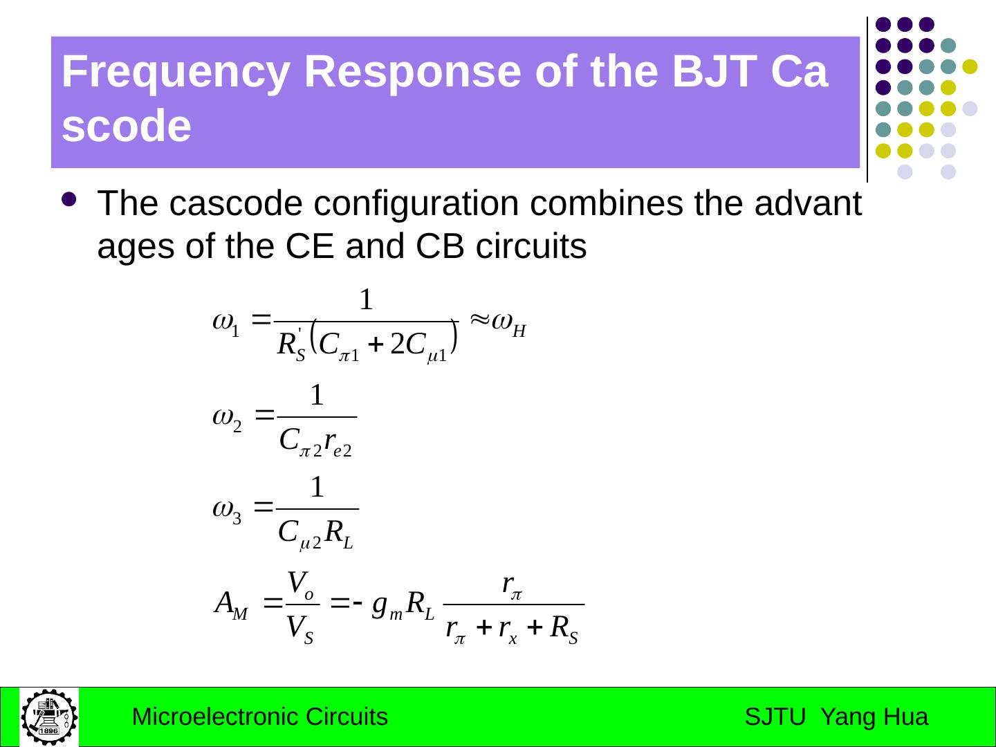
1 .Chapter 7 Frequency Response Introduction 7.1 s-Domain analysis: poles,zeros and bode plots 7.2 the amplifier transfer function 7.3 Low-frequency response of the common-source and common-emitter amplifier 7.4 High-frequency response of the CS and CE amplifiers 7.5 The CB, CG and cascode configurations
2 .Introduction Why shall we study the frequency response? Actual transistors exhibit charge storage phenomena that limit the speed and frequency of their operation. Aims: the emphasis in this chapter is on analysis. focusing attention on the mechanisms that limit frequency response and on methods for extending amplifier bandwidth.
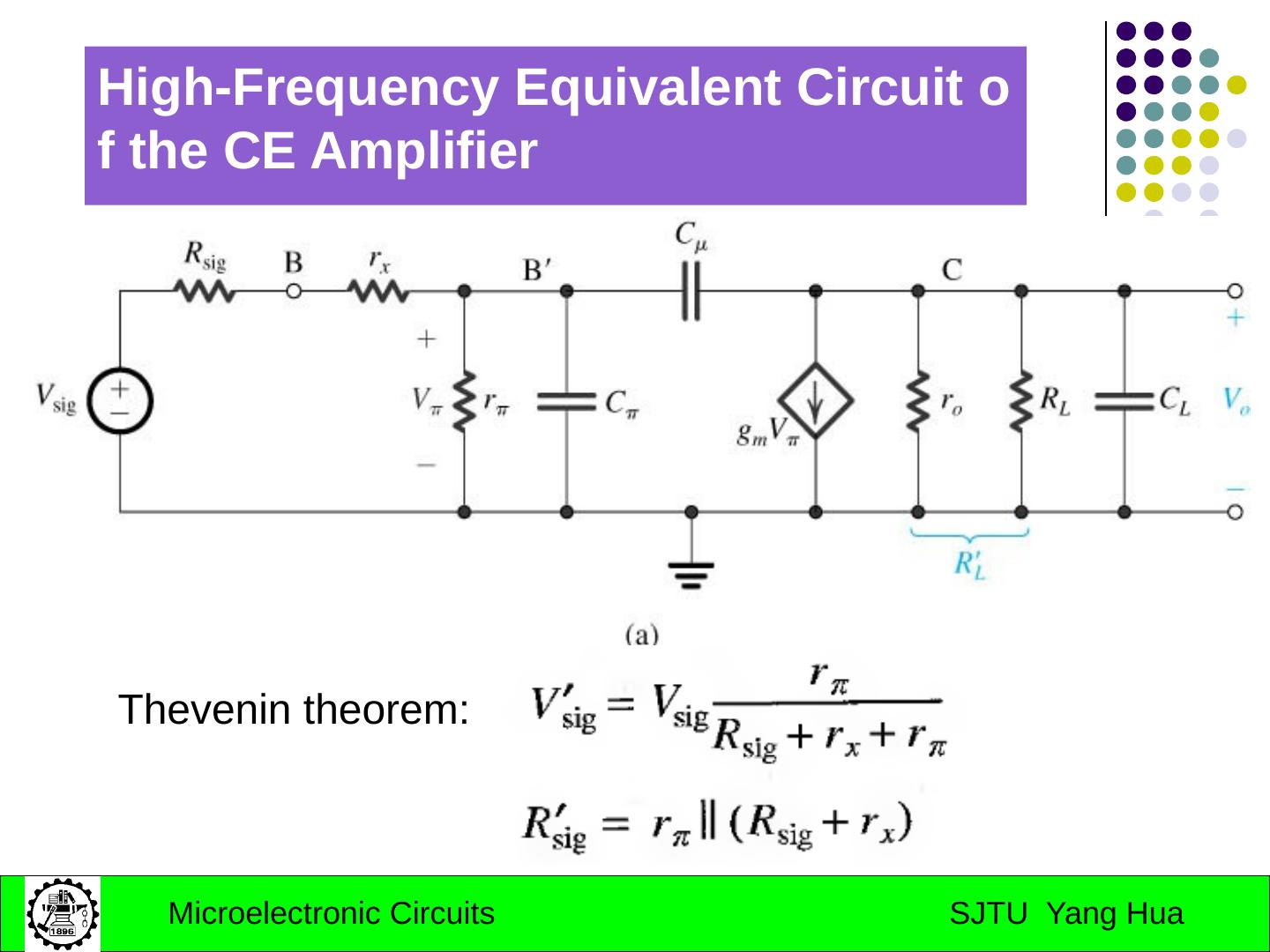
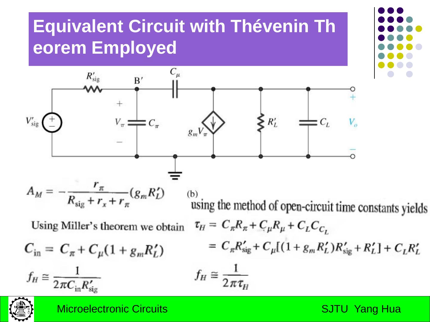
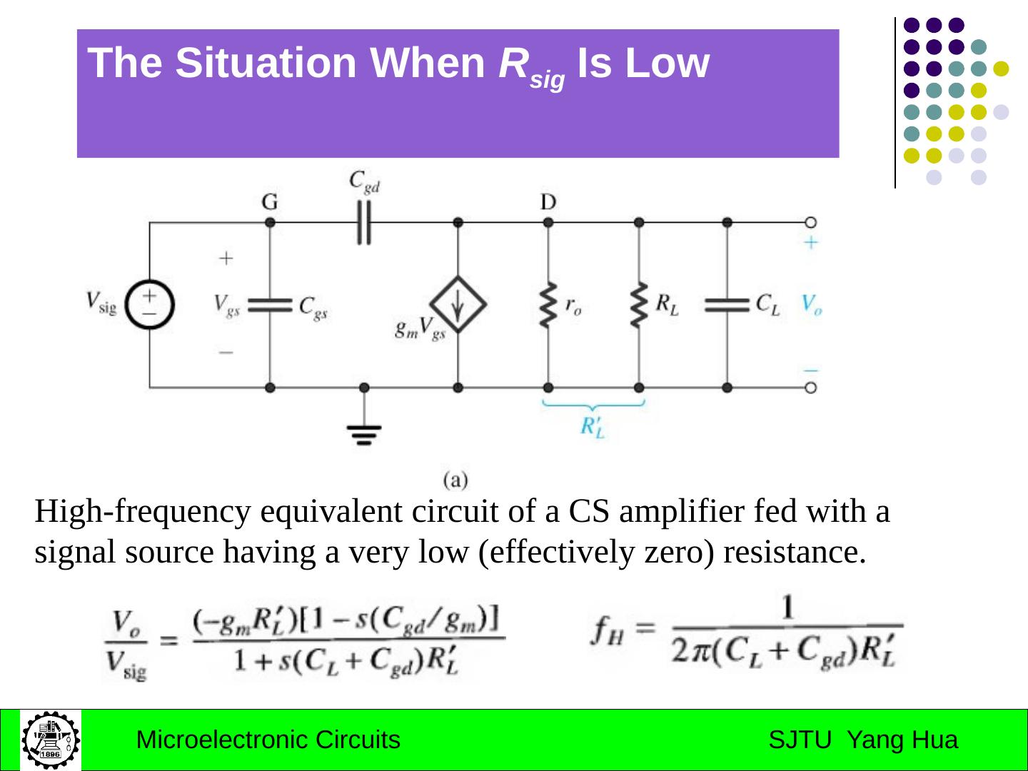
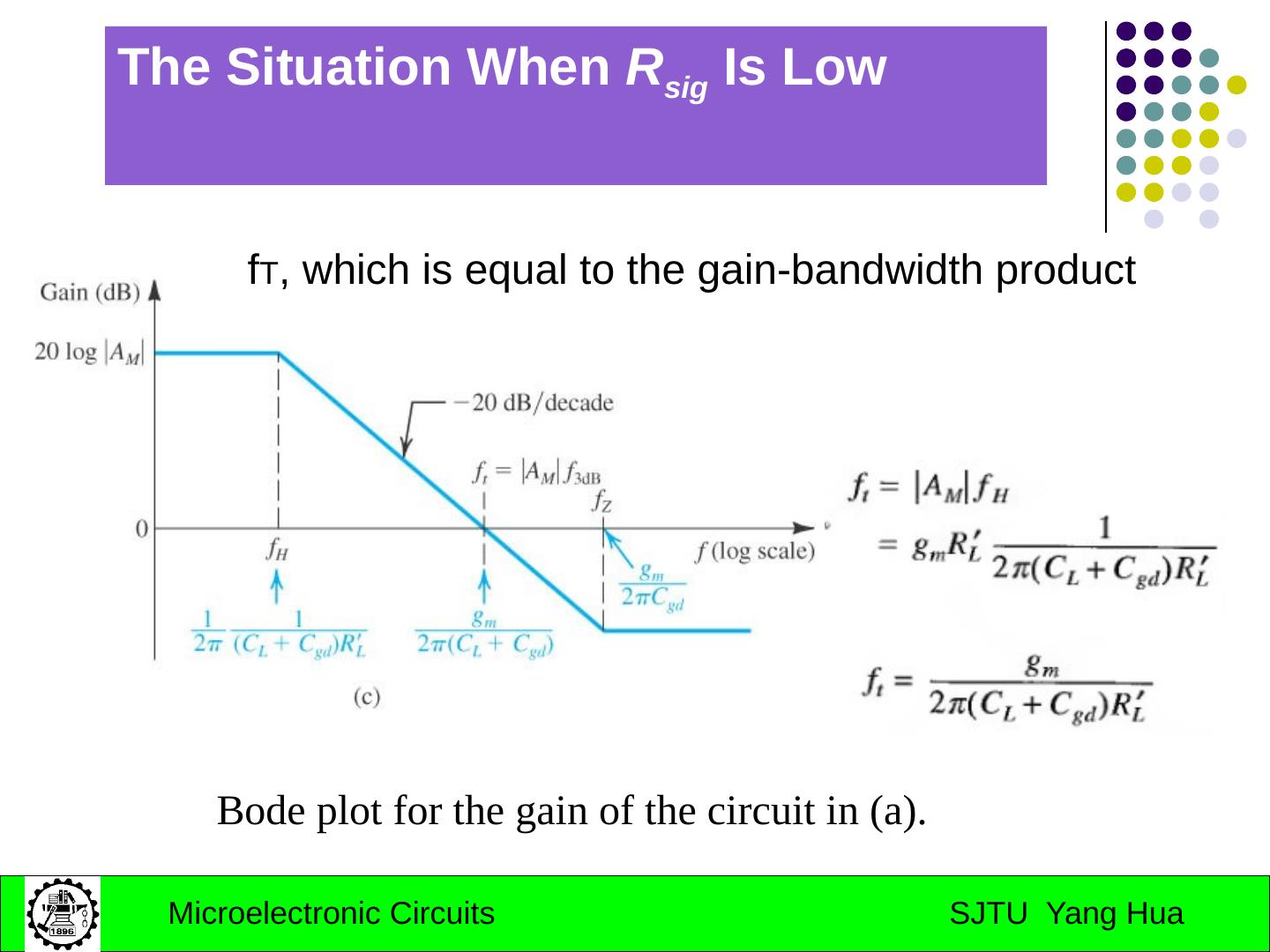
3 .Three parts: s-Domain analysis and the amplifier transfer function (April 13,2008) High frequency model of BJT and MOS; Low-frequency and High-frequency response of the common-source and common-emitter amplifier (April 15,2008) Frequency response of cascode , Emitter and source followers and differential amplifier (April 22,2008)
4 .Part I: s-Domain analysis Zeros and poles Bode plots The amplifier transfer function
5 .7.1 s-Domain analysis– Frequency Response Transfer function: poles, zeros Examples: high pass and low pass Bode plots: Determining the 3-dB frequency
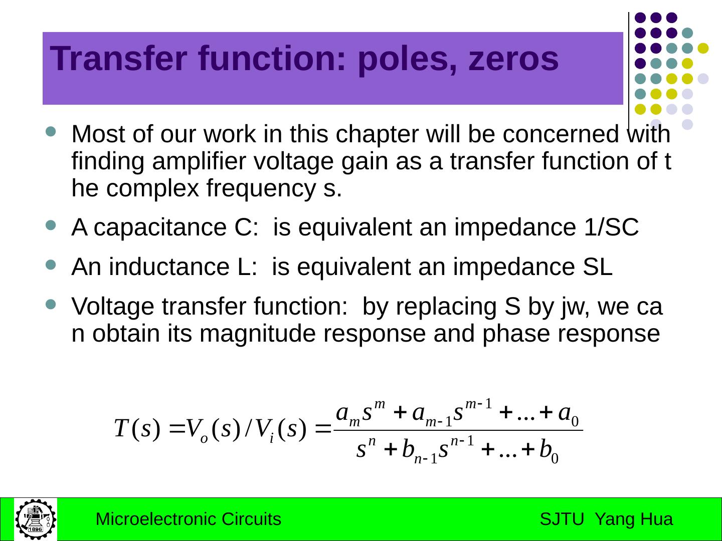
6 .Transfer function: poles, zeros Most of our work in this chapter will be concerned with finding amplifier voltage gain as a transfer function of the complex frequency s. A capacitance C: is equivalent an impedance 1/SC An inductance L: is equivalent an impedance SL Voltage transfer function: by replacing S by jw , we can obtain its magnitude response and phase response
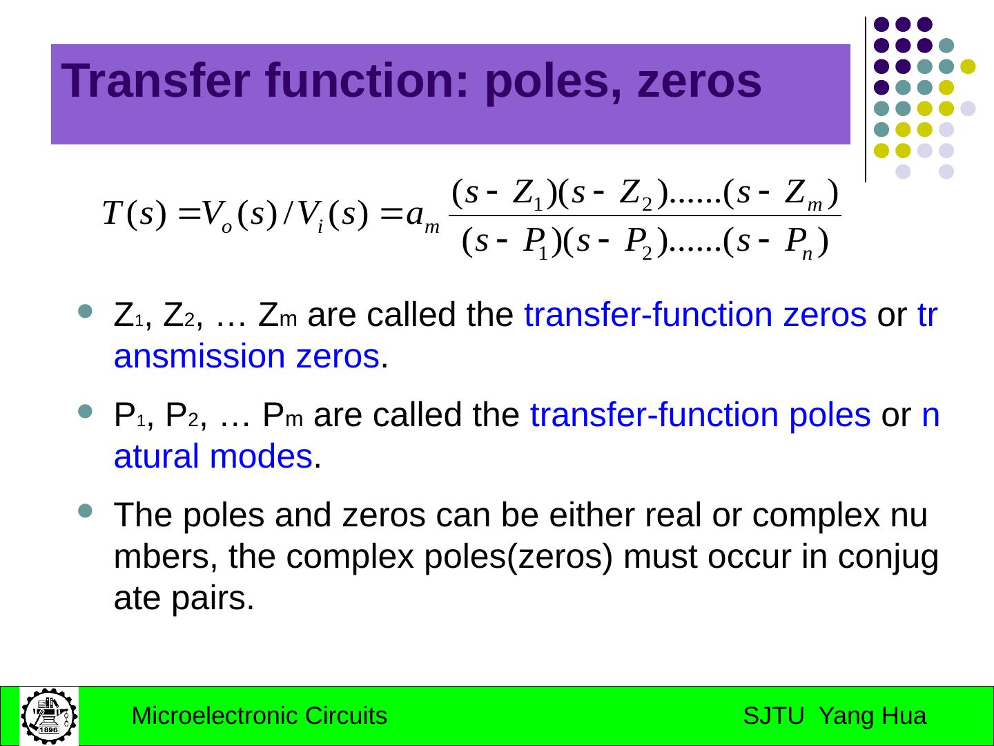
7 .Transfer function: poles, zeros Z 1 , Z 2 , … Z m are called the transfer-function zeros or transmission zeros . P 1 , P 2 , … P m are called the transfer-function poles or natural modes . The poles and zeros can be either real or complex numbers, the complex poles(zeros ) must occur in conjugate pairs.
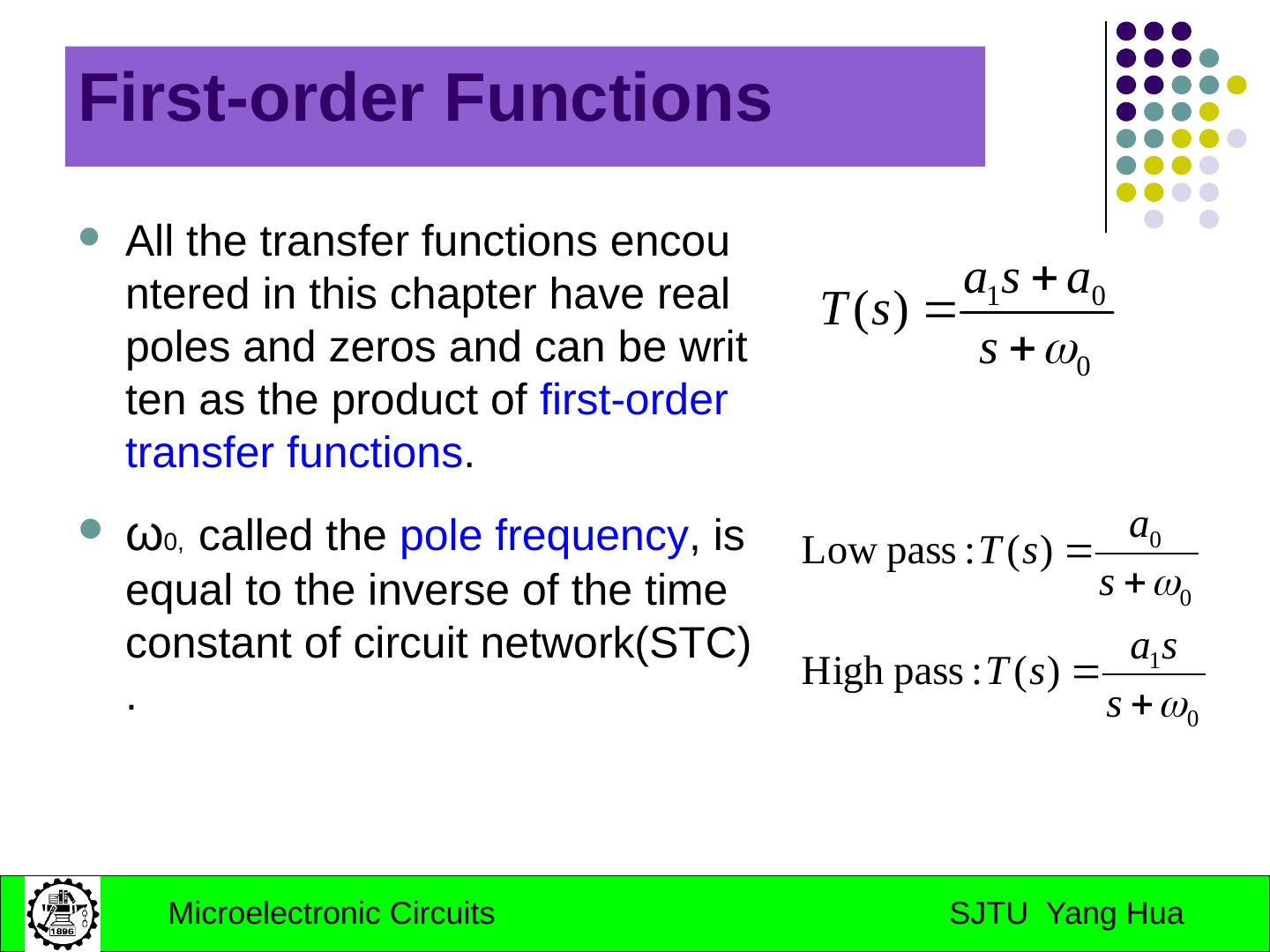
8 .First-order Functions All the transfer functions encountered in this chapter have real poles and zeros and can be written as the product of first-order transfer functions . ω 0, called the pole frequency , is equal to the inverse of the time constant of circuit network(STC ).
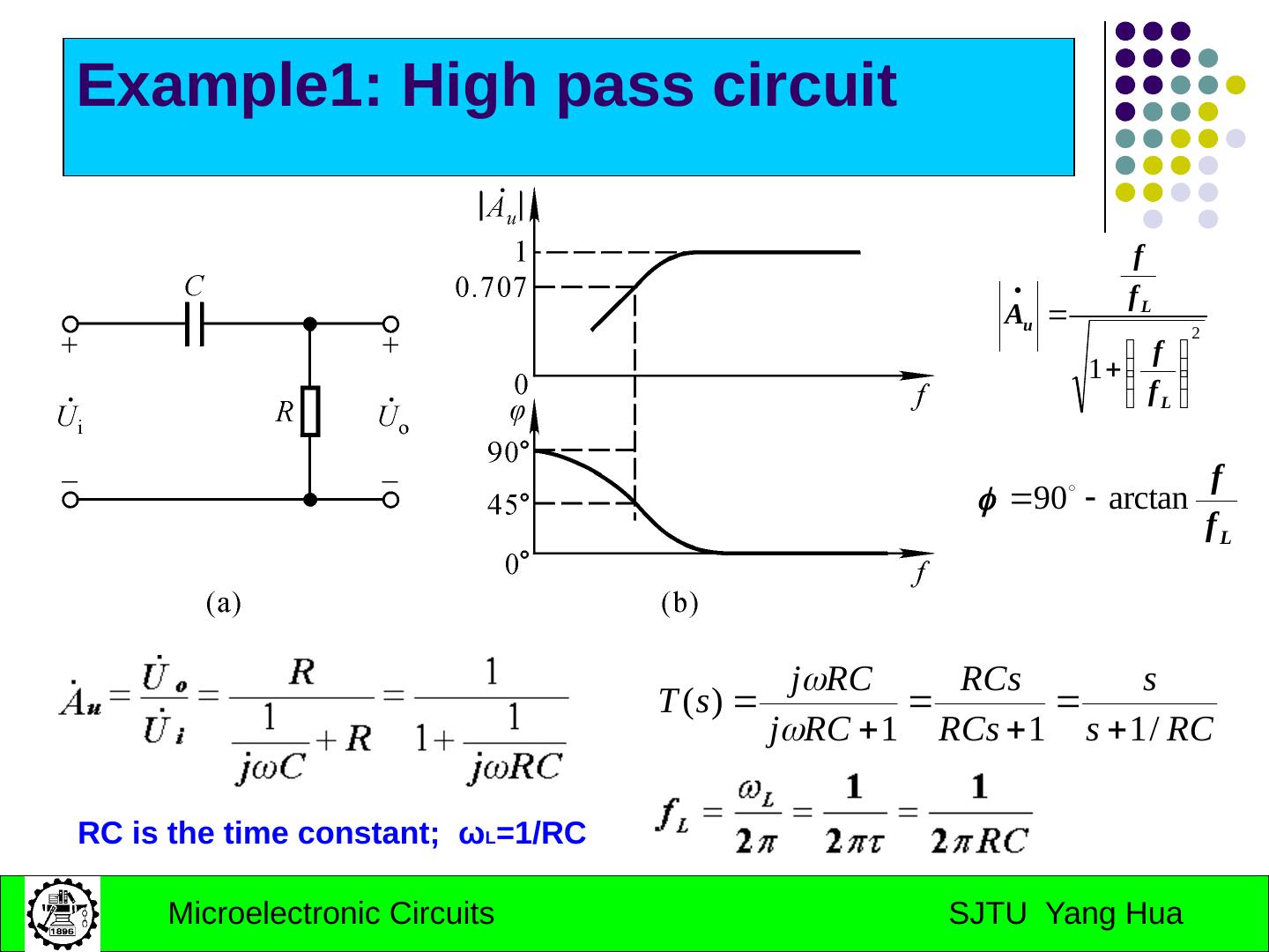
9 .Example1: High pass circuit RC is the time constant; ω L =1/RC
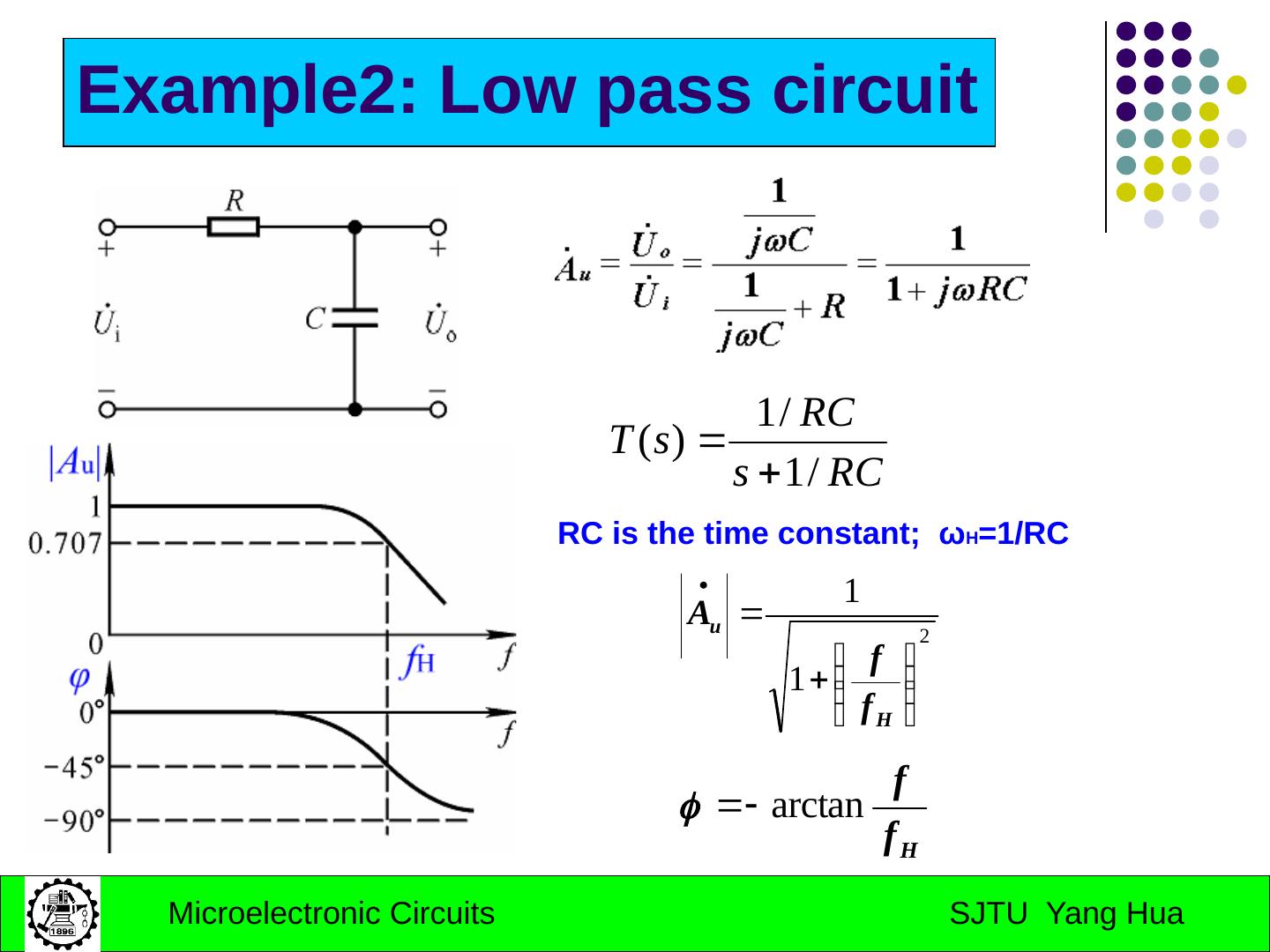
10 .Example2: Low pass circuit RC is the time constant; ω H =1/RC
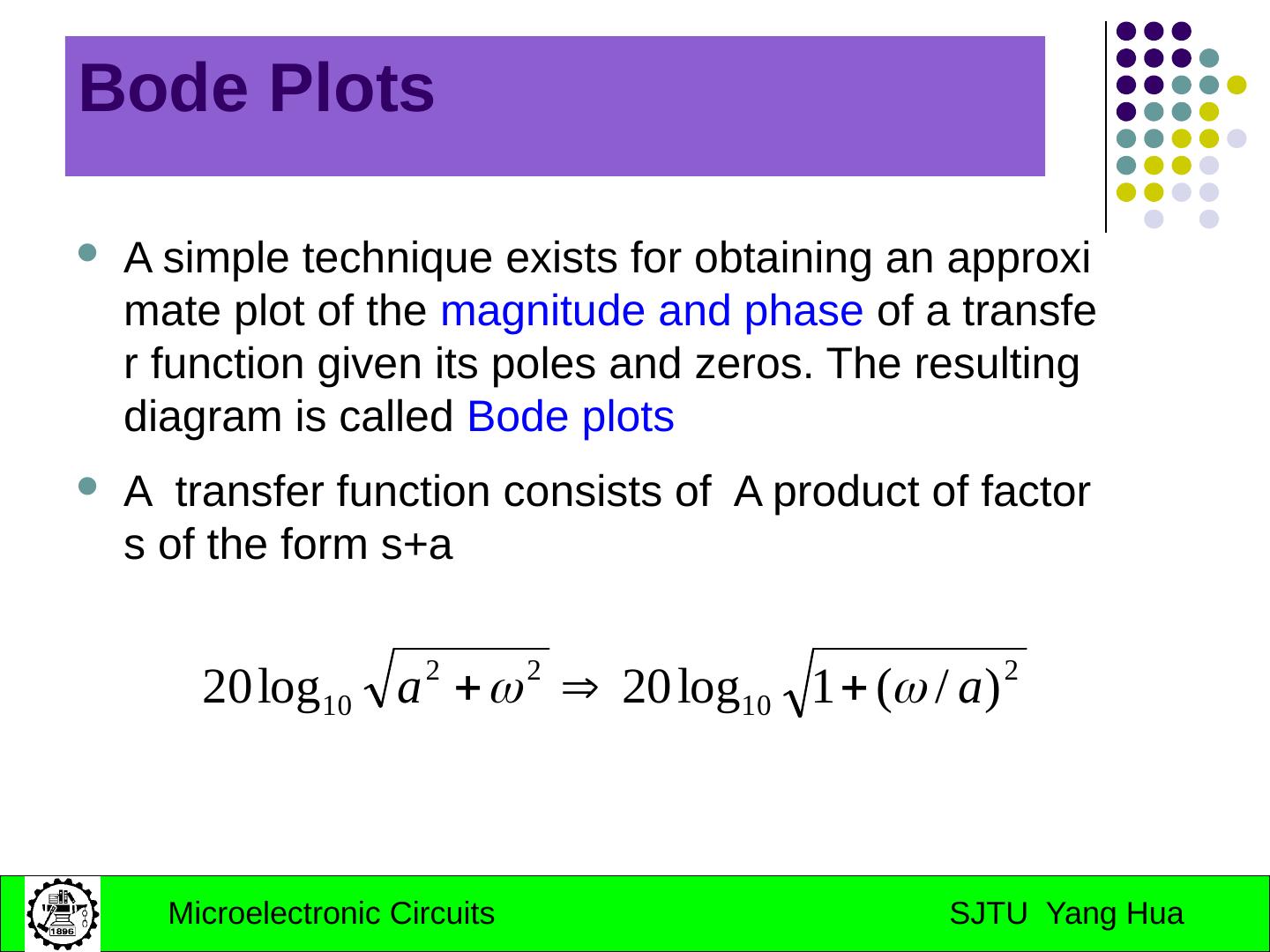
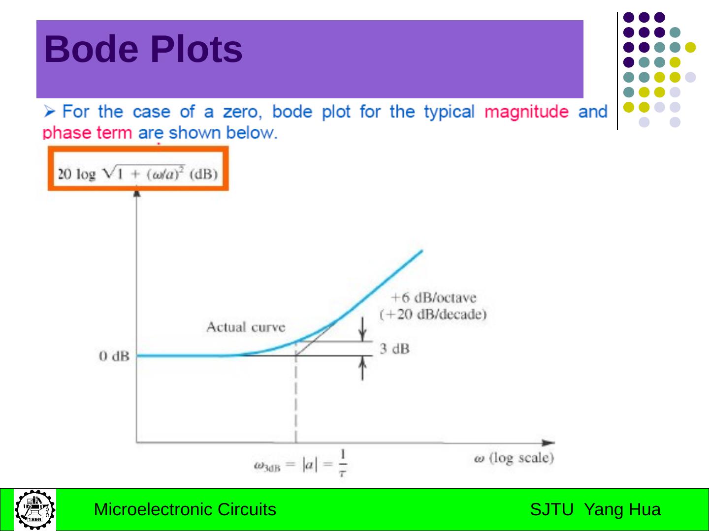
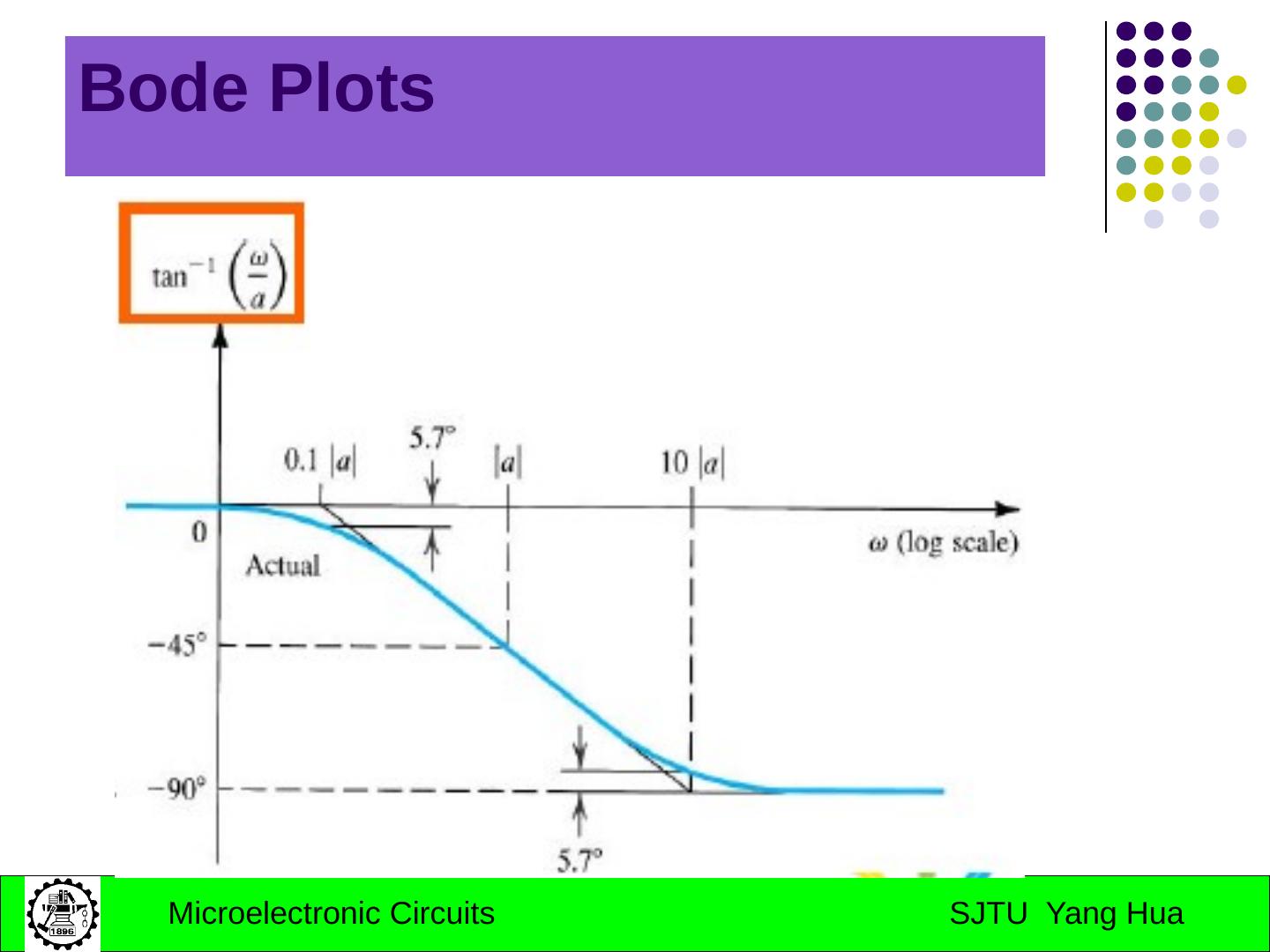
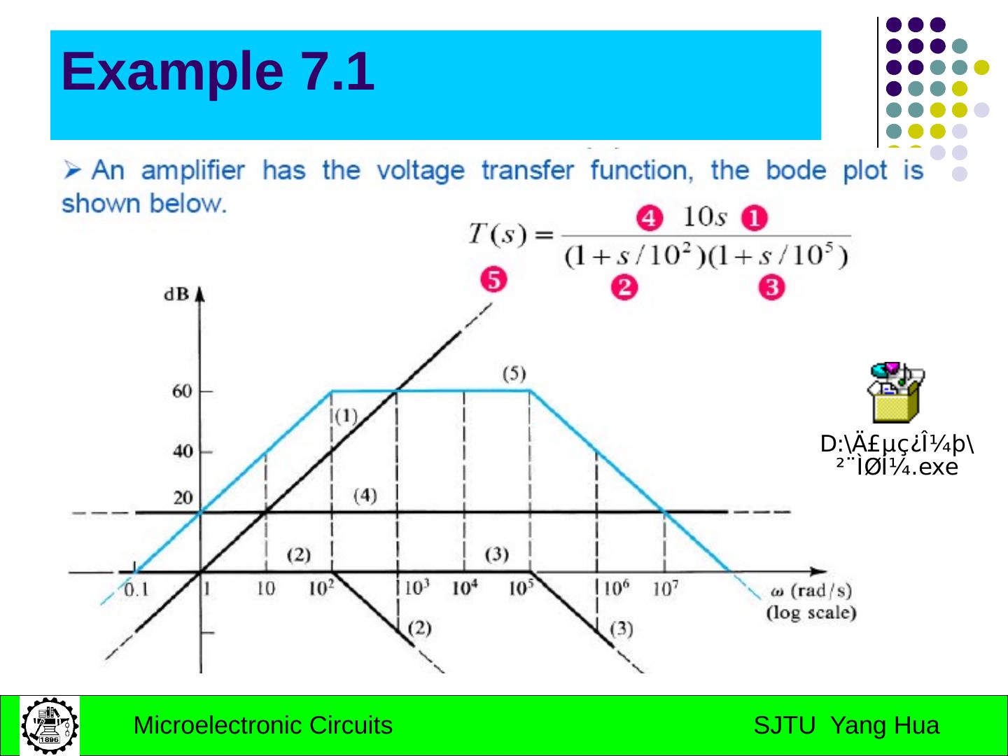
11 .Bode Plots A simple technique exists for obtaining an approximate plot of the magnitude and phase of a transfer function given its poles and zeros. The resulting diagram is called Bode plots A transfer function consists of A product of factors of the form s+a
12 .Bode Plots
13 .Bode Plots
14 .Example 7.1
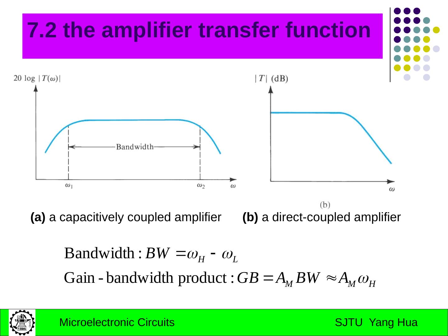
15 .7.2 the amplifier transfer function (a) a capacitively coupled amplifier (b) a direct-coupled amplifier
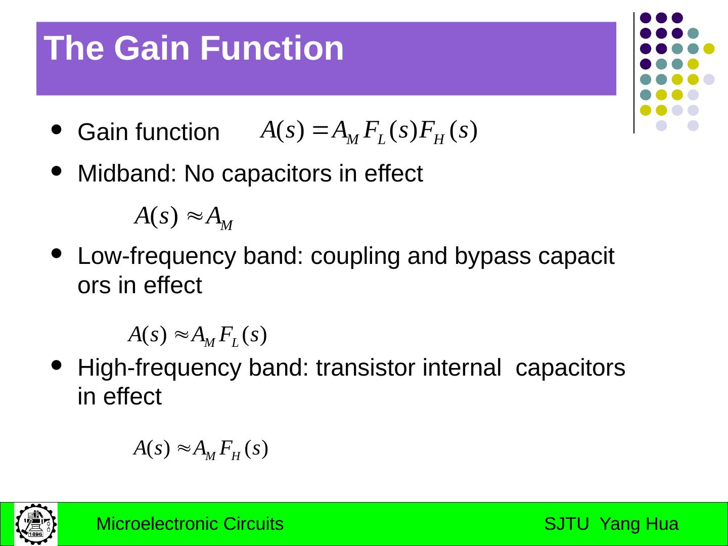
16 .The Gain Function Gain function Midband : No capacitors in effect Low-frequency band: coupling and bypass capacitors in effect High-frequency band: transistor internal capacitors in effect
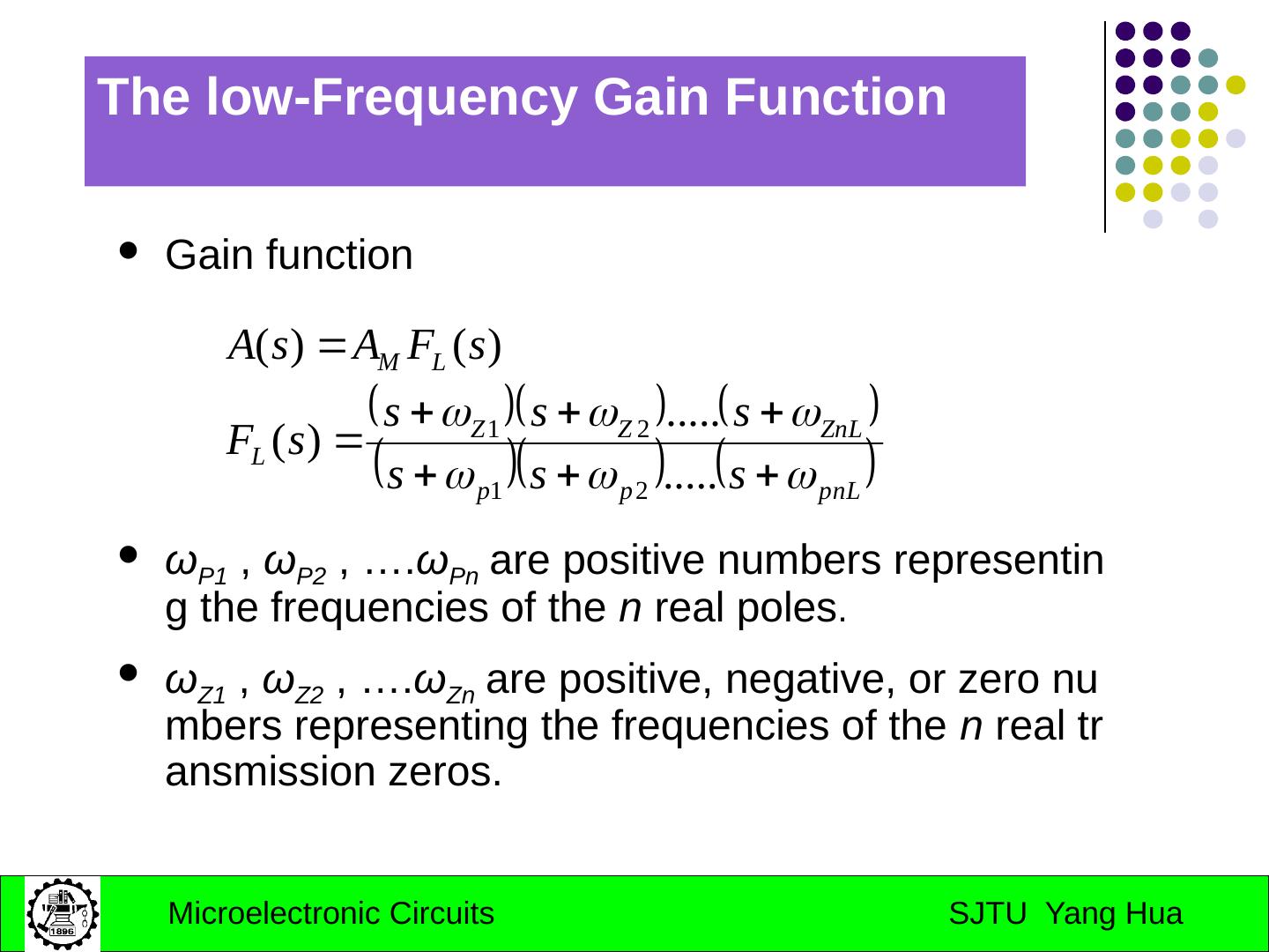
17 .The low-Frequency Gain Function Gain function ω P1 , ω P2 , …. ω Pn are positive numbers representing the frequencies of the n real poles . ω Z1 , ω Z2 , …. ω Zn are positive, negative, or zero numbers representing the frequencies of the n real transmission zeros.
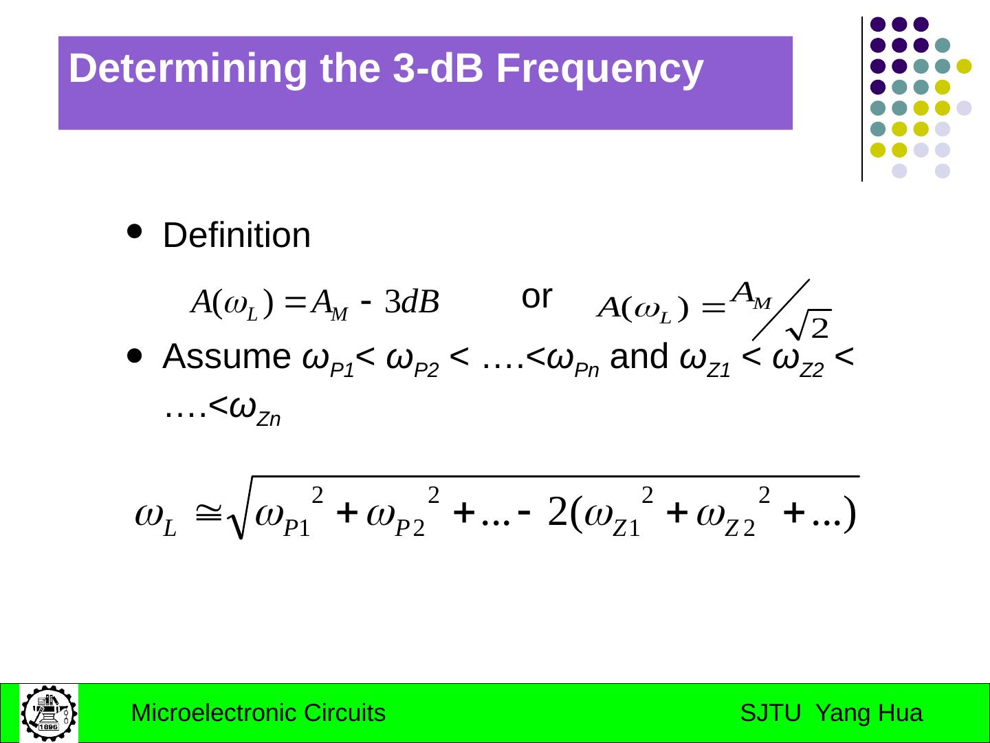
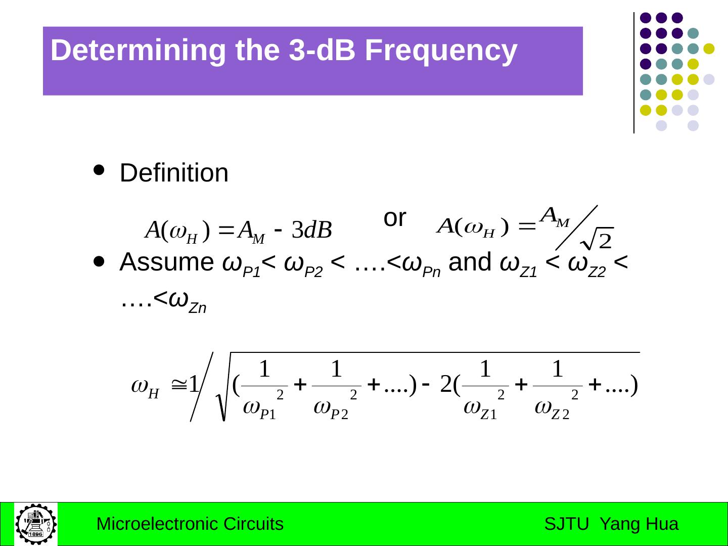
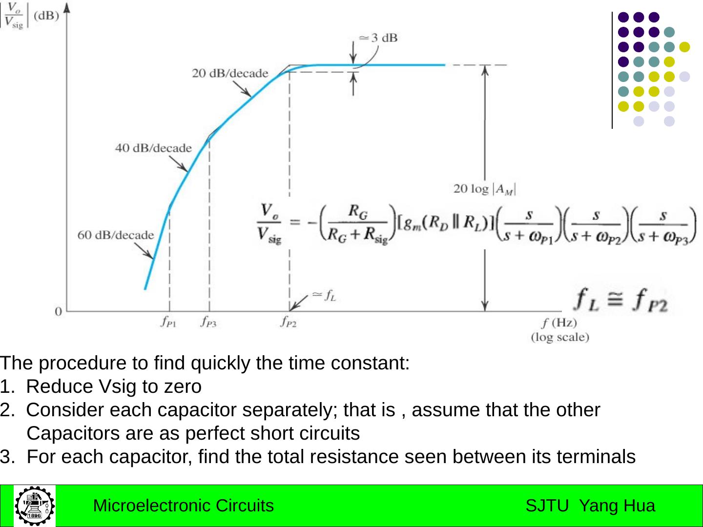
18 .Determining the 3-dB Frequency Definition or Assume ω P1 < ω P2 < ….< ω Pn and ω Z1 < ω Z2 < ….< ω Zn
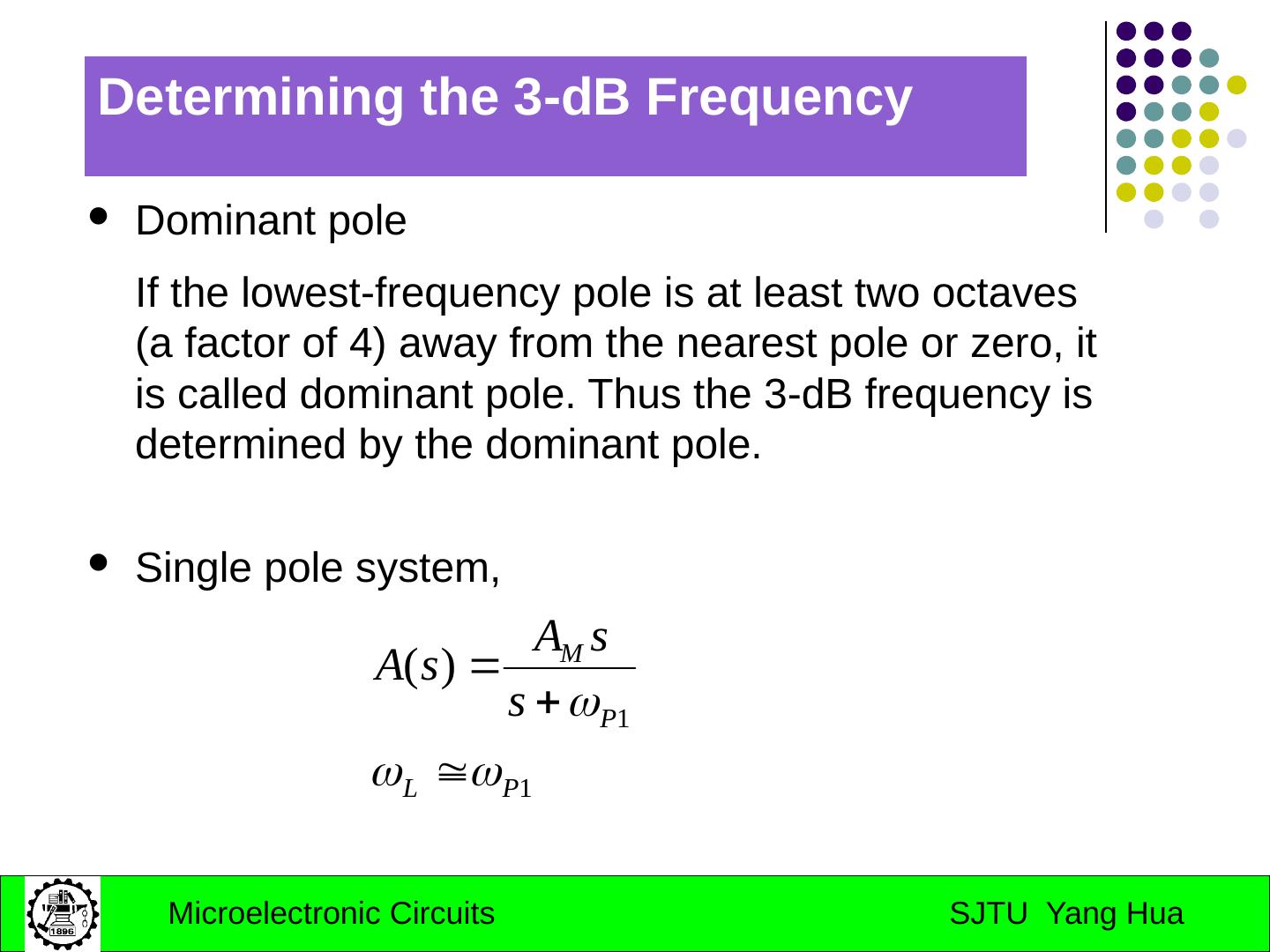
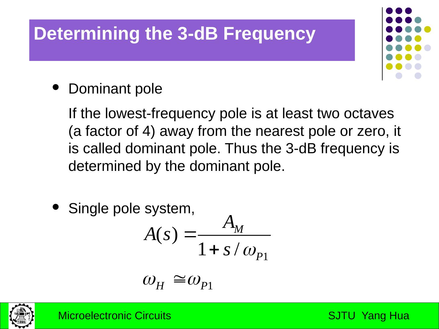
19 .Determining the 3-dB Frequency Dominant pole If the lowest-frequency pole is at least two octaves (a factor of 4) away from the nearest pole or zero, it is called dominant pole. Thus the 3-dB frequency is determined by the dominant pole. Single pole system,
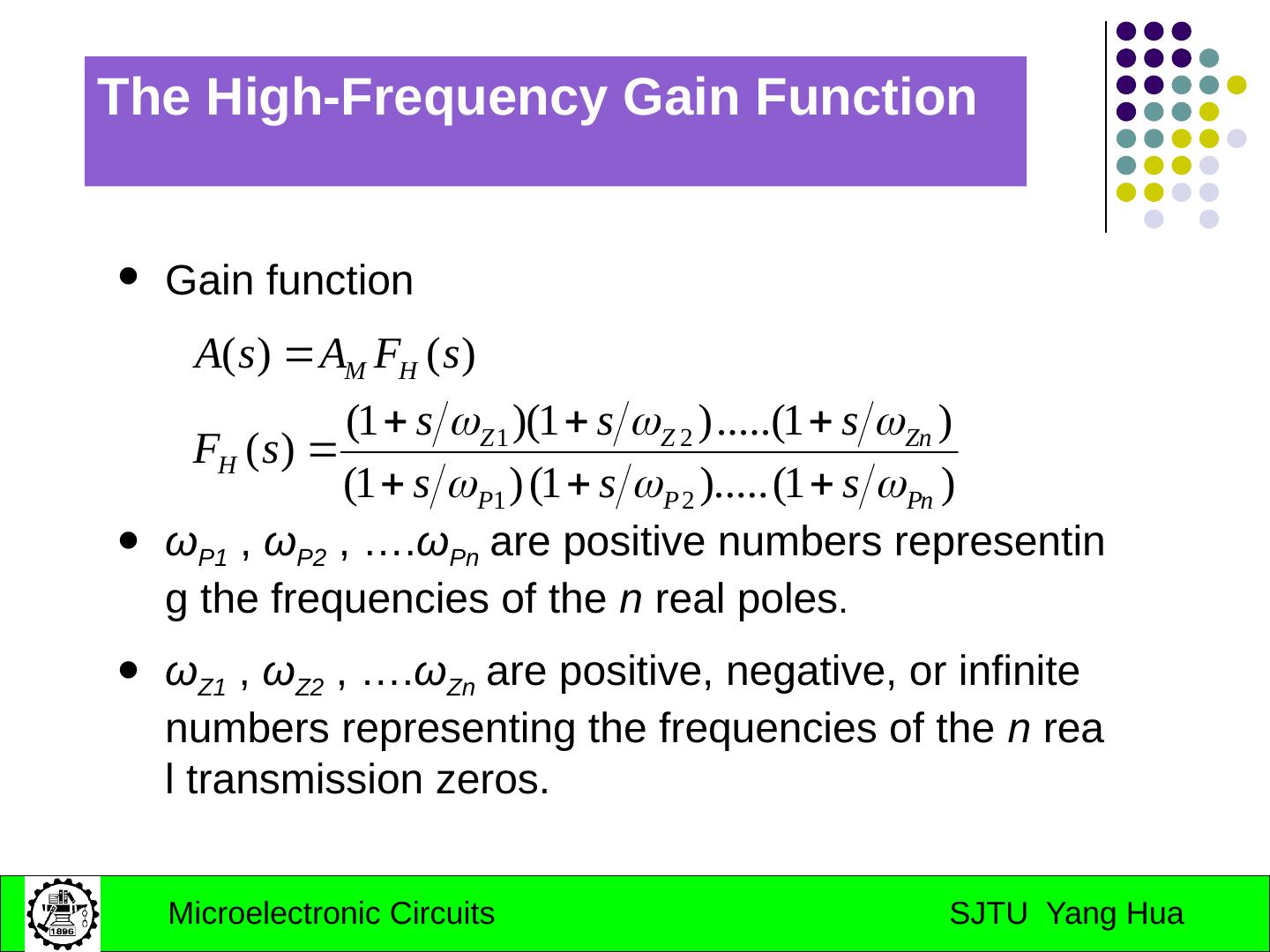
20 .The High-Frequency Gain Function Gain function ω P1 , ω P2 , …. ω Pn are positive numbers representing the frequencies of the n real poles . ω Z1 , ω Z2 , …. ω Zn are positive, negative, or infinite numbers representing the frequencies of the n real transmission zeros.
21 .The High-Frequency Gain Function Gain function ω P1 , ω P2 , …. ω Pn are positive numbers representing the frequencies of the n real poles . ω Z1 , ω Z2 , …. ω Zn are positive, negative, or infinite numbers representing the frequencies of the n real transmission zeros.
22 .The High-Frequency Gain Function Gain function ω P1 , ω P2 , …. ω Pn are positive numbers representing the frequencies of the n real poles . ω Z1 , ω Z2 , …. ω Zn are positive, negative, or infinite numbers representing the frequencies of the n real transmission zeros.
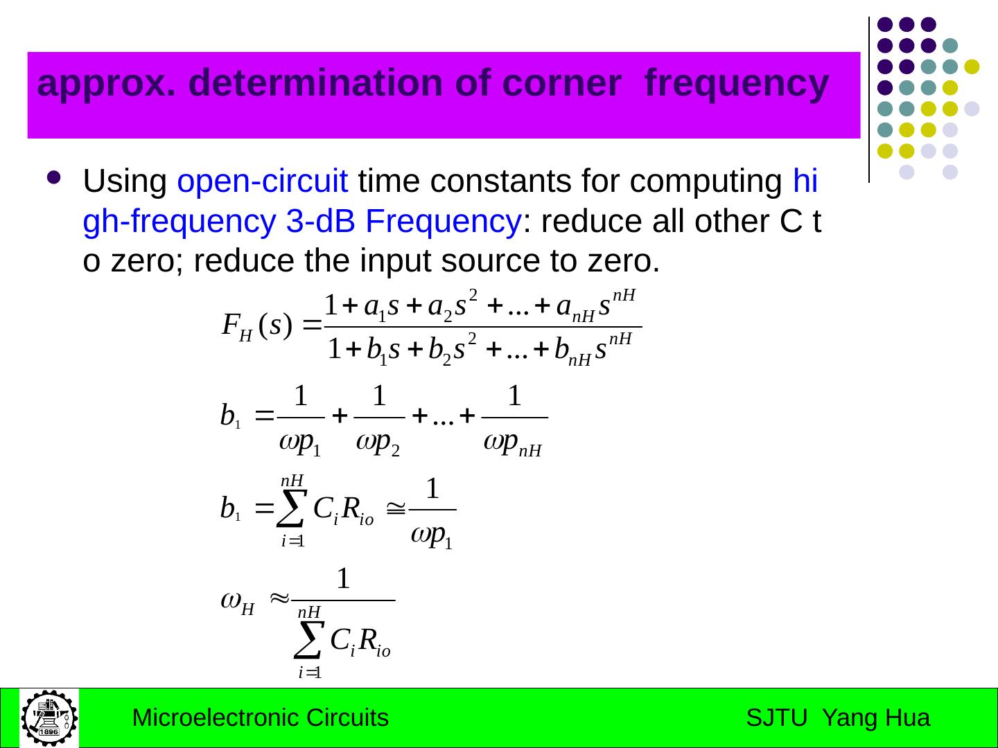
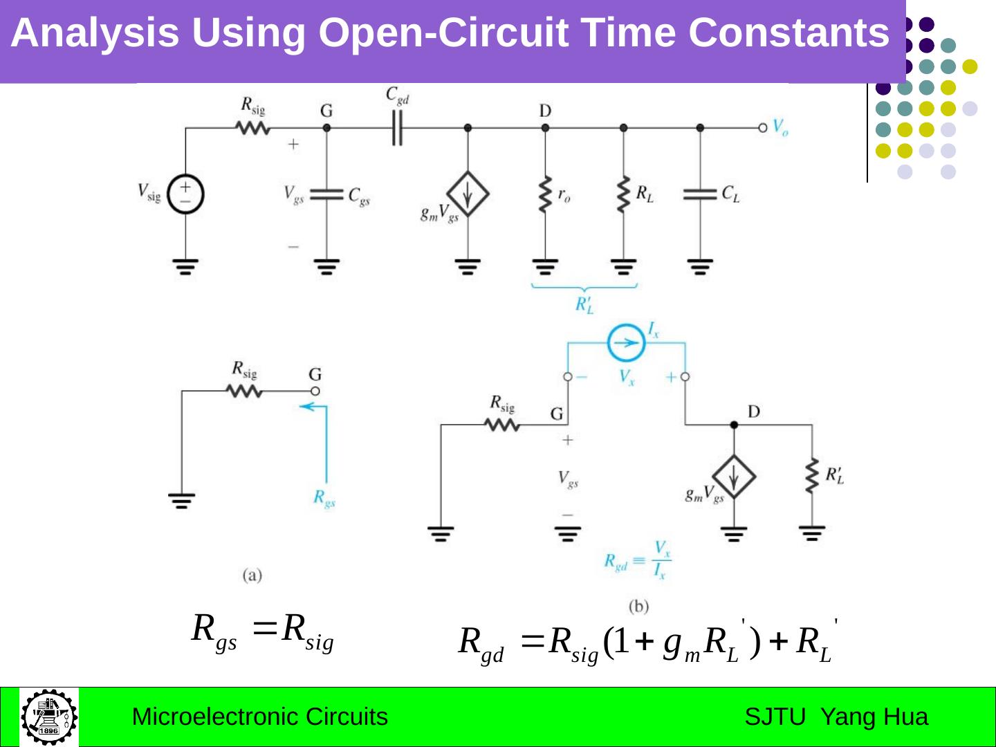
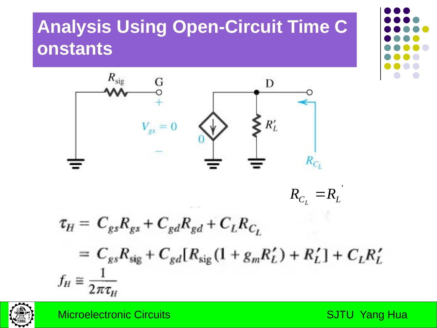
23 .approx. determination of corner frequency Using open-circuit time constants for computing high-frequency 3-dB Frequency : reduce all other C to zero; reduce the input source to zero.
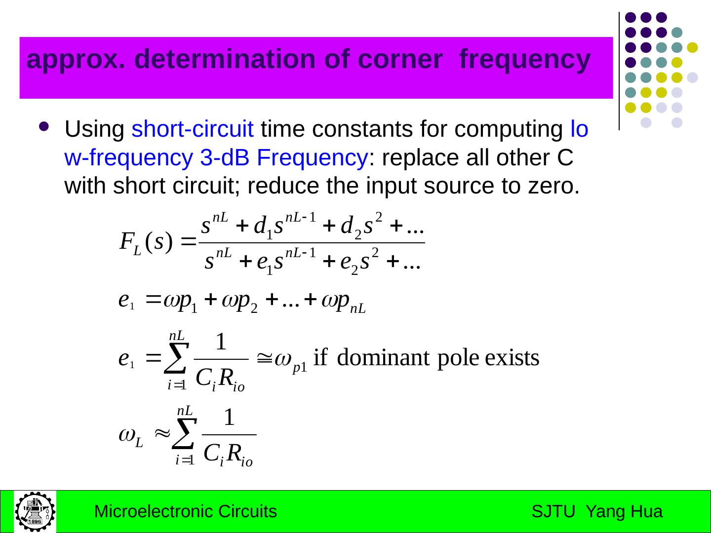
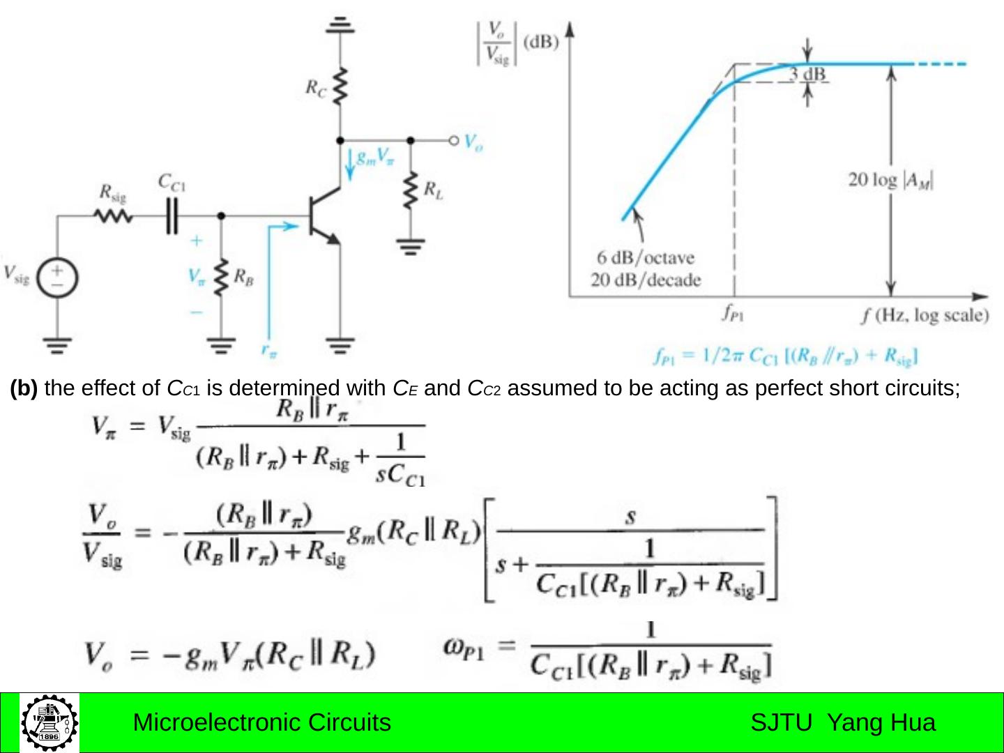
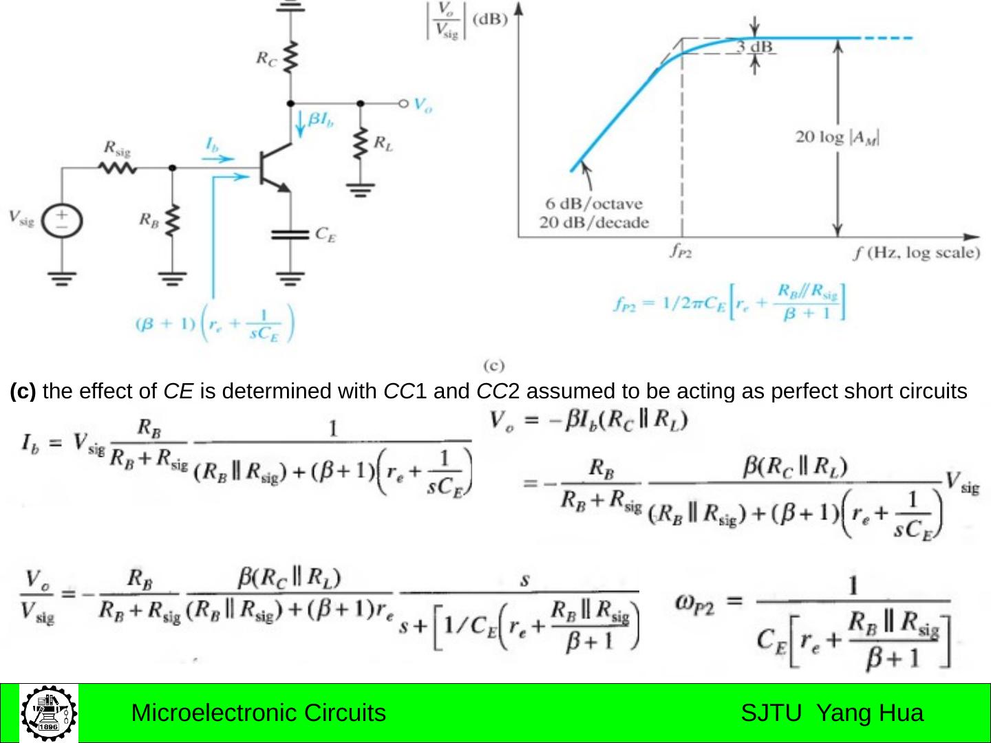
24 .approx. determination of corner frequency Using short-circuit time constants for computing low-frequency 3-dB Frequency : replace all other C with short circuit; reduce the input source to zero.
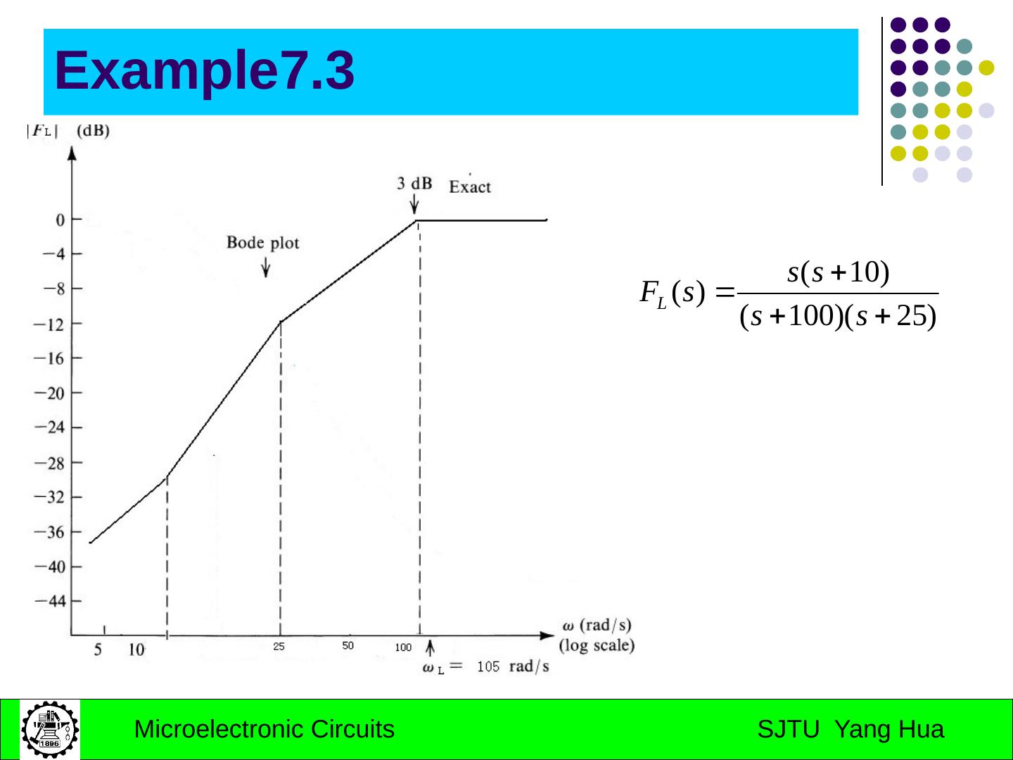
25 .Example7.3
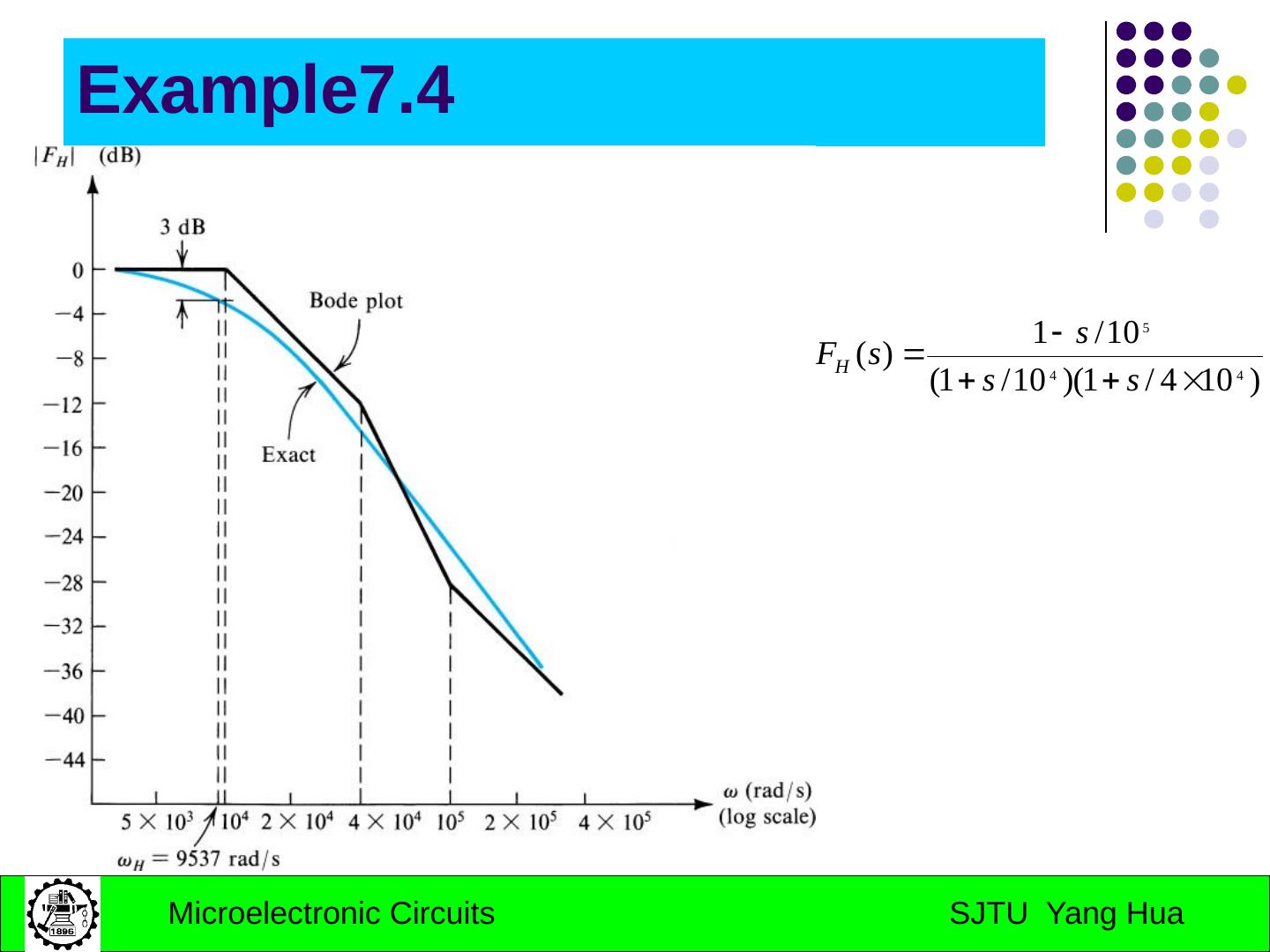
26 .Example7.4
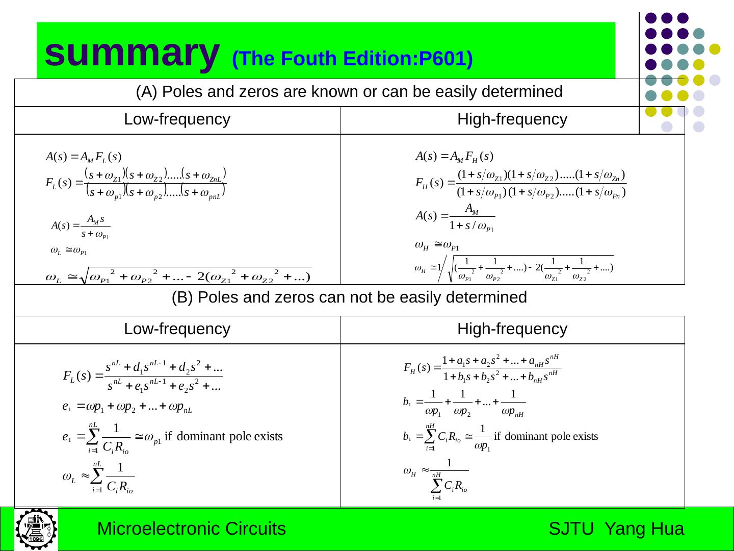
27 .summary (The Fouth Edition:P601) (A) Poles and zeros are known or can be easily determined Low-frequency High-frequency (B) Poles and zeros can not be easily determined Low-frequency High-frequency
28 .Homework April 17th, 2008 7.1; 7.2; 7.7; 7.10
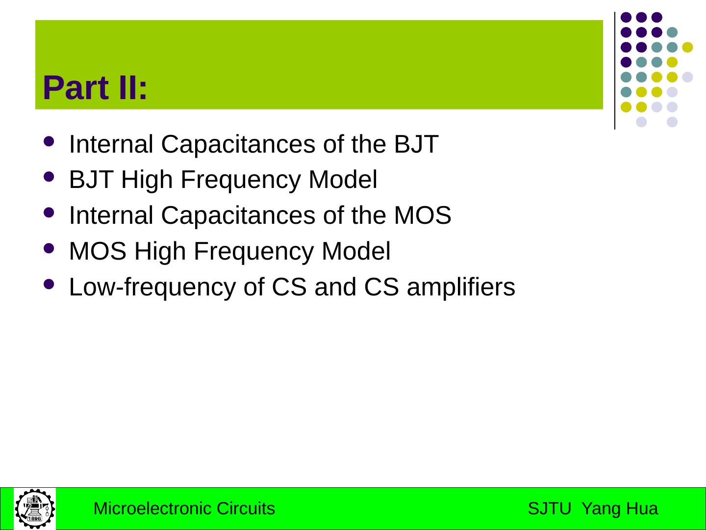
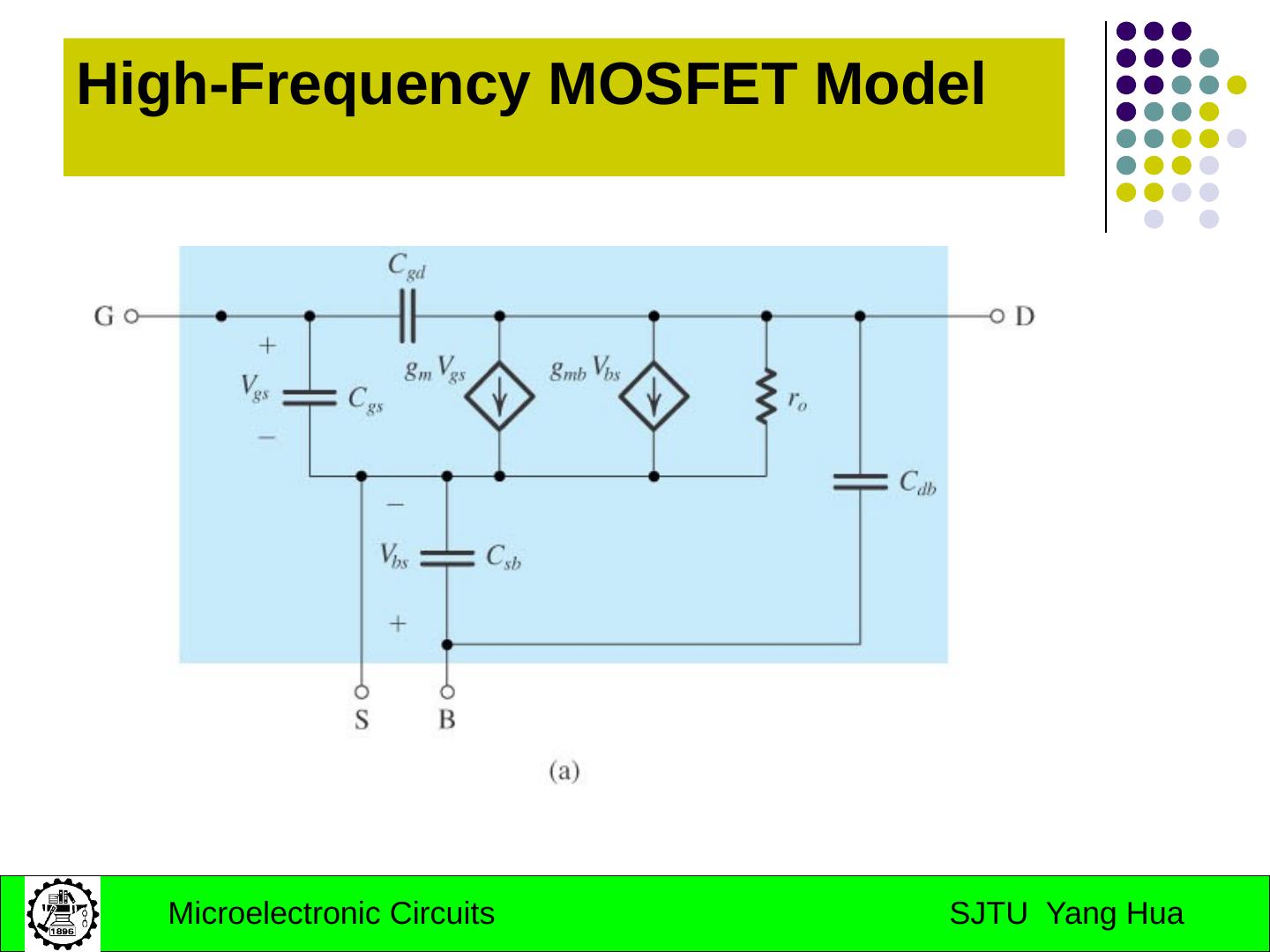
29 .Part II: Internal Capacitances of the BJT BJT High Frequency Model Internal Capacitances of the MOS MOS High Frequency Model Low-frequency of CS and CS amplifiers


