- 快召唤伙伴们来围观吧
- 微博 QQ QQ空间 贴吧
- 文档嵌入链接
- 复制
- 微信扫一扫分享
- 已成功复制到剪贴板
控制器
展开查看详情
1 .Chapter 3 Digital Logic Structures
2 .3- 2 Complete Example A blinking traffic sign No lights on 1 & 2 on 1, 2, 3, & 4 on 1, 2, 3, 4, & 5 on (repeat as long as switch is turned on) DANGER MOVE RIGHT 1 2 3 4 5
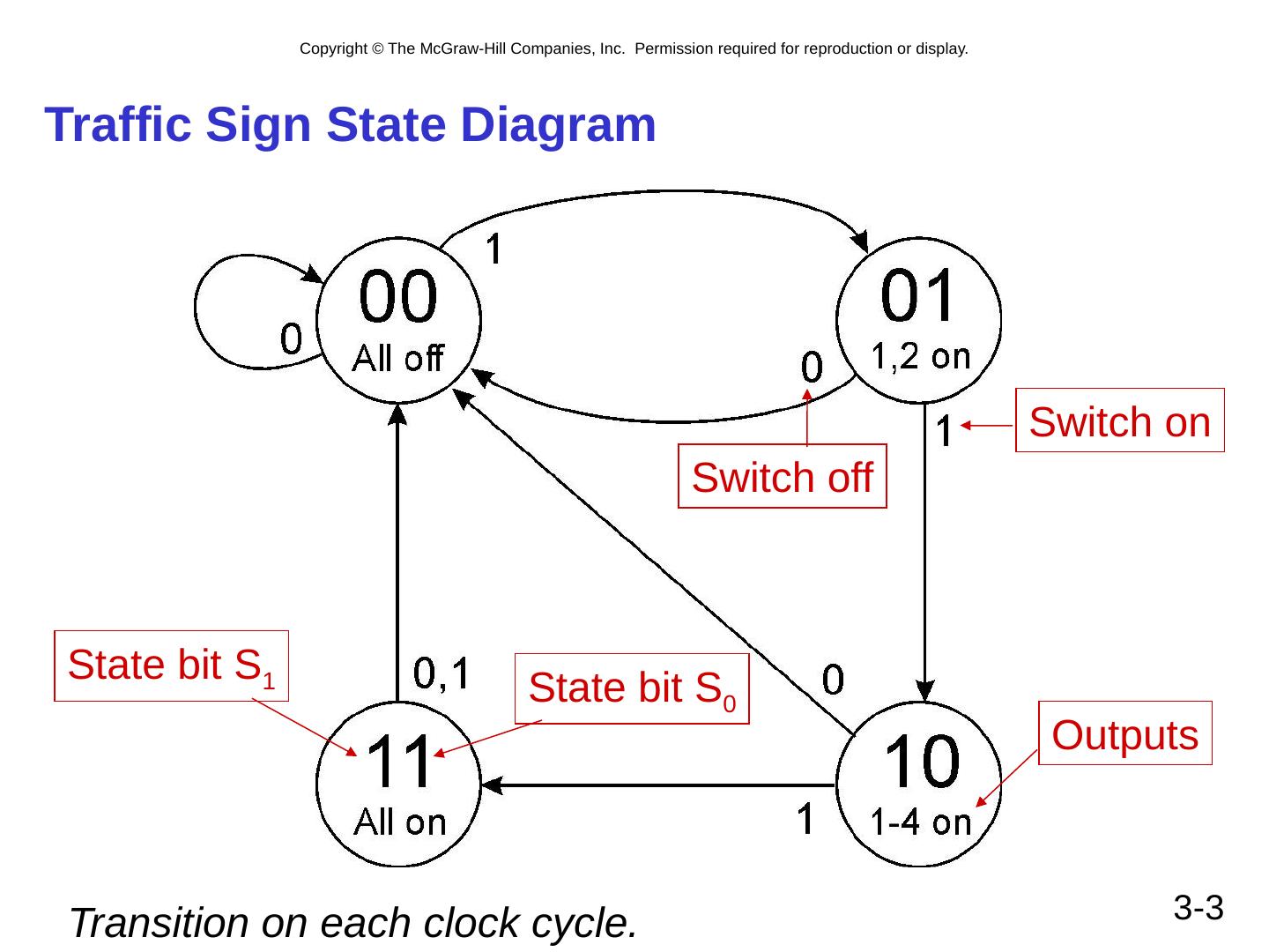
3 .3- 3 Traffic Sign State Diagram State bit S 1 State bit S 0 Switch on Switch off Outputs Transition on each clock cycle.
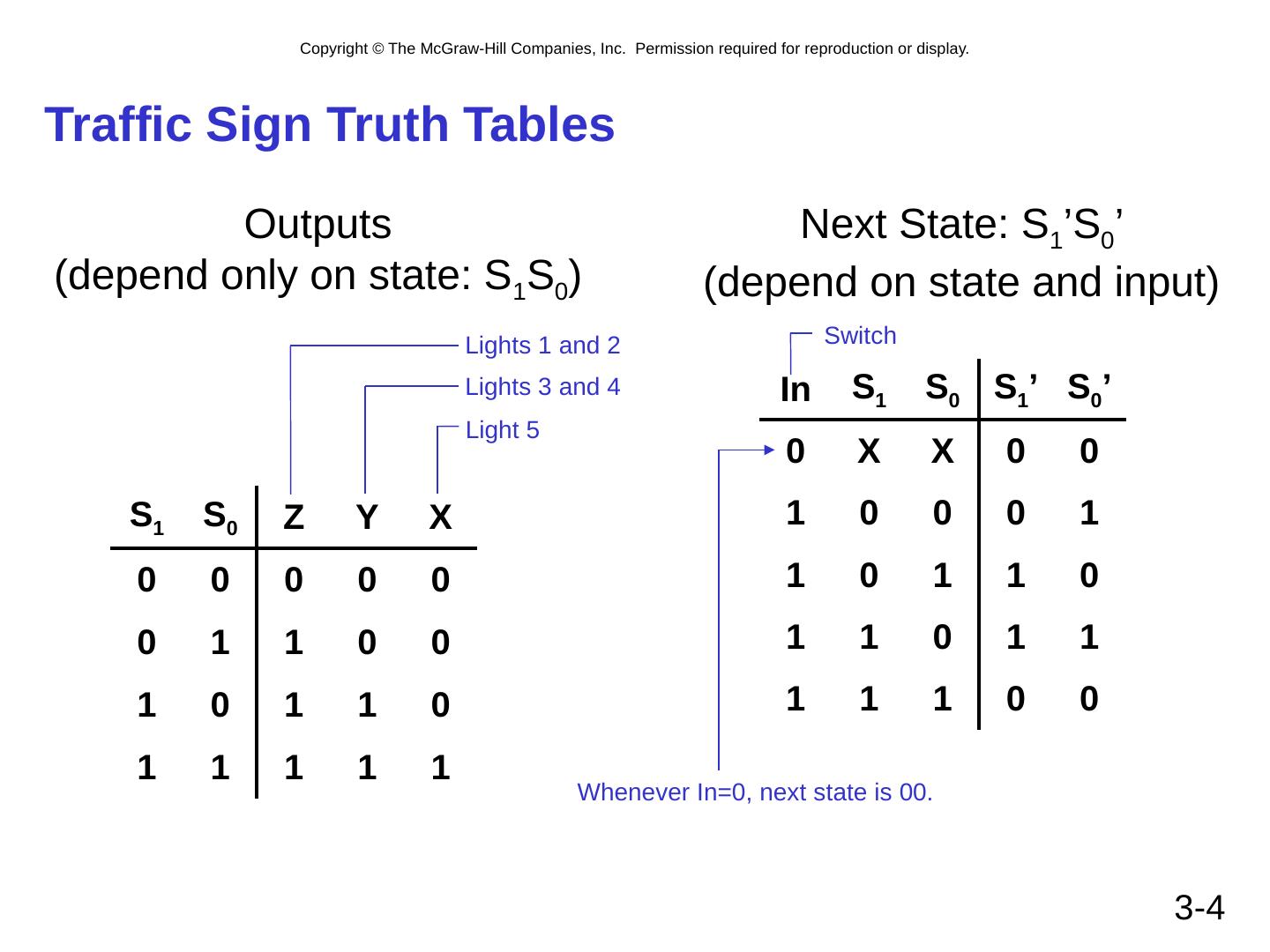
4 .3- 4 Traffic Sign Truth Tables Outputs (depend only on state: S 1 S 0 ) S 1 S 0 Z Y X 0 0 0 0 0 0 1 1 0 0 1 0 1 1 0 1 1 1 1 1 Lights 1 and 2 Lights 3 and 4 Light 5 Next State: S 1 ’S 0 ’ (depend on state and input) In S 1 S 0 S 1 ’ S 0 ’ 0 X X 0 0 1 0 0 0 1 1 0 1 1 0 1 1 0 1 1 1 1 1 0 0 Switch Whenever In=0, next state is 00.
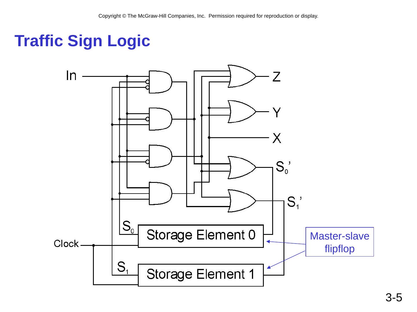
5 .3- 5 Traffic Sign Logic Master-slave flipflop
6 .3- 5 Traffic Sign Logic Master-slave flipflop
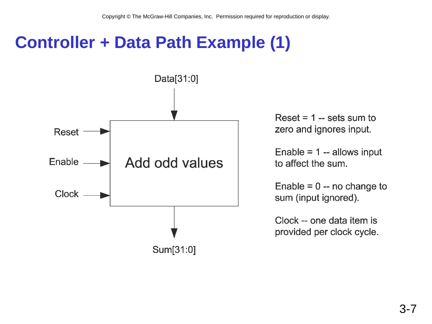
7 .Controller + Data Path Example (1) 3- 7
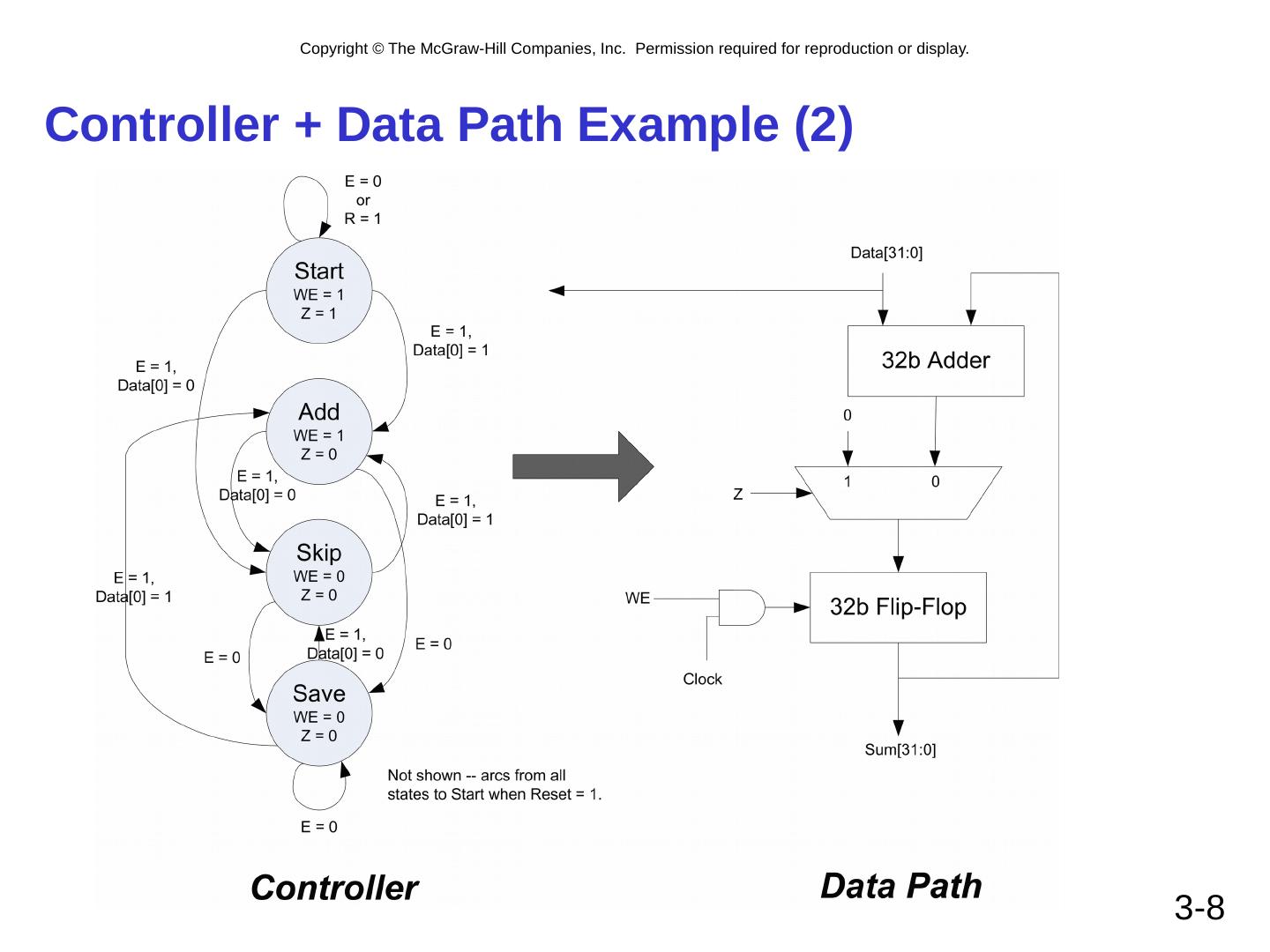
8 .Controller + Data Path Example (2) 3- 8
9 .3- 9 From Logic to Computer Data Path The data path of a computer is all the logic used to process information. See the data path of the LC-3 on next slide. Combinational Logic Decoders -- convert instructions into control signals, access memory Multiplexers – select inputs and outputs ALU (Arithmetic and Logic Unit) – performs operations on data Sequential Logic State machine -- coordinate control signals and data movement Registers and latches -- storage elements
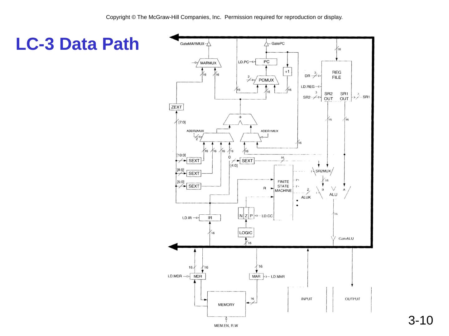
10 .3- 10 LC-3 Data Path
