- 快召唤伙伴们来围观吧
- 微博 QQ QQ空间 贴吧
- 文档嵌入链接
- 复制
- 微信扫一扫分享
- 已成功复制到剪贴板
07 State Machines XX
展开查看详情
1 .Lecture 7 Topics Latches Flip Flops Algorithmic State Machines
2 .Latches
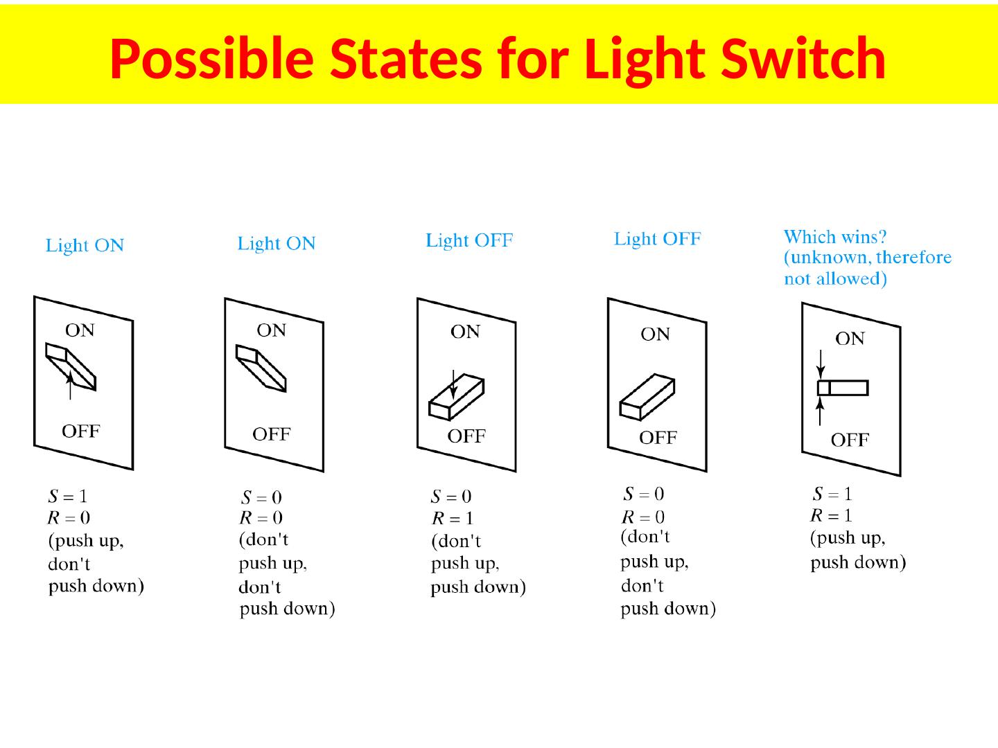
3 .Possible States for Light Switch
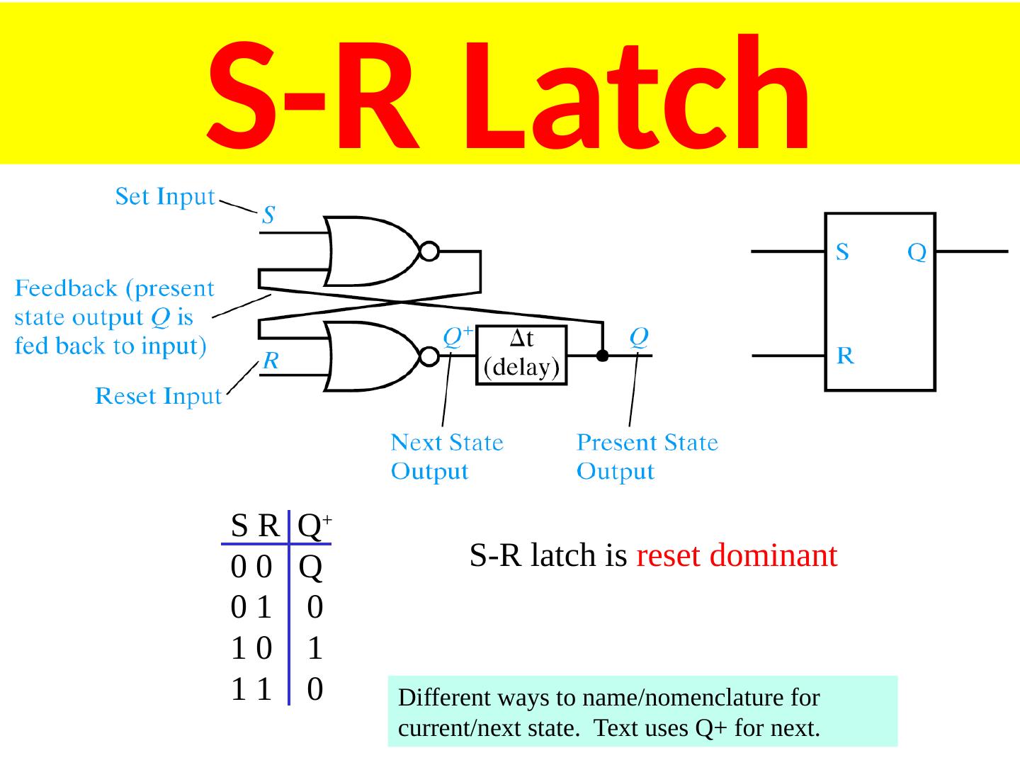
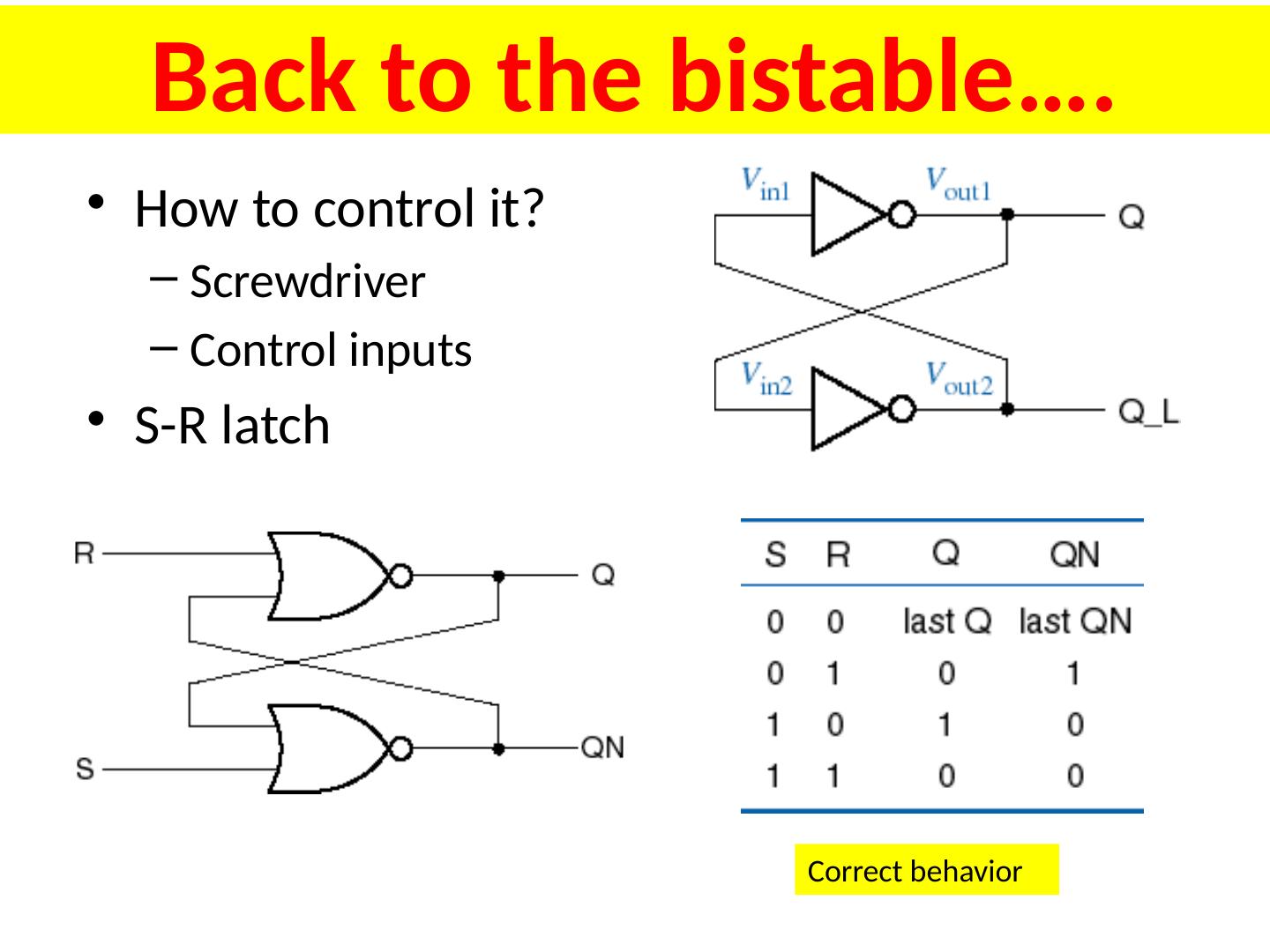
4 .S-R Latch S R Q + 0 0 Q 0 1 0 1 0 1 1 1 0 S-R latch is reset dominant Different ways to name/nomenclature for current/next state. Text uses Q+ for next.
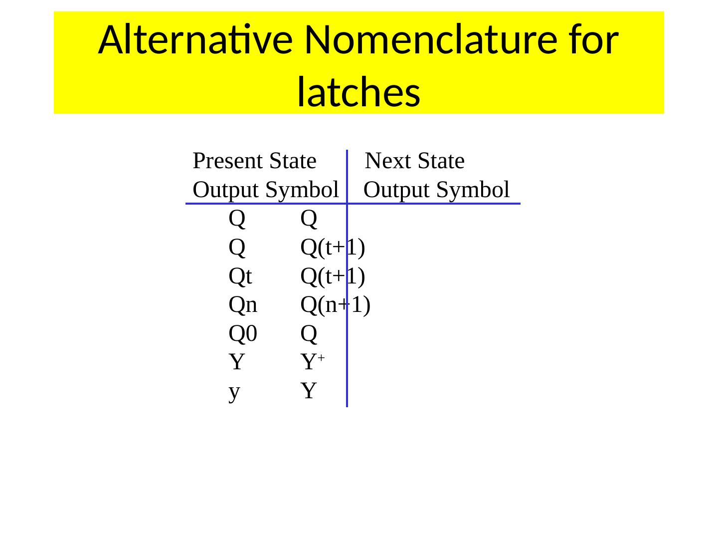
5 .Alternative Nomenclature for latches Present State Next State Output Symbol Output Symbol Q Q Q Q(t+1) Qt Q(t+1) Qn Q(n+1) Q0 Q Y Y + y Y
6 .S-R Latch States S-R latch is reset dominant
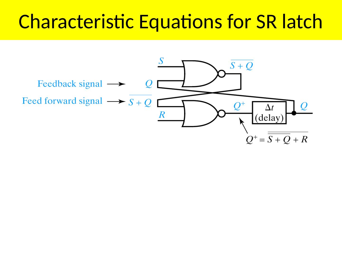
7 .Characteristic Equations for SR latch
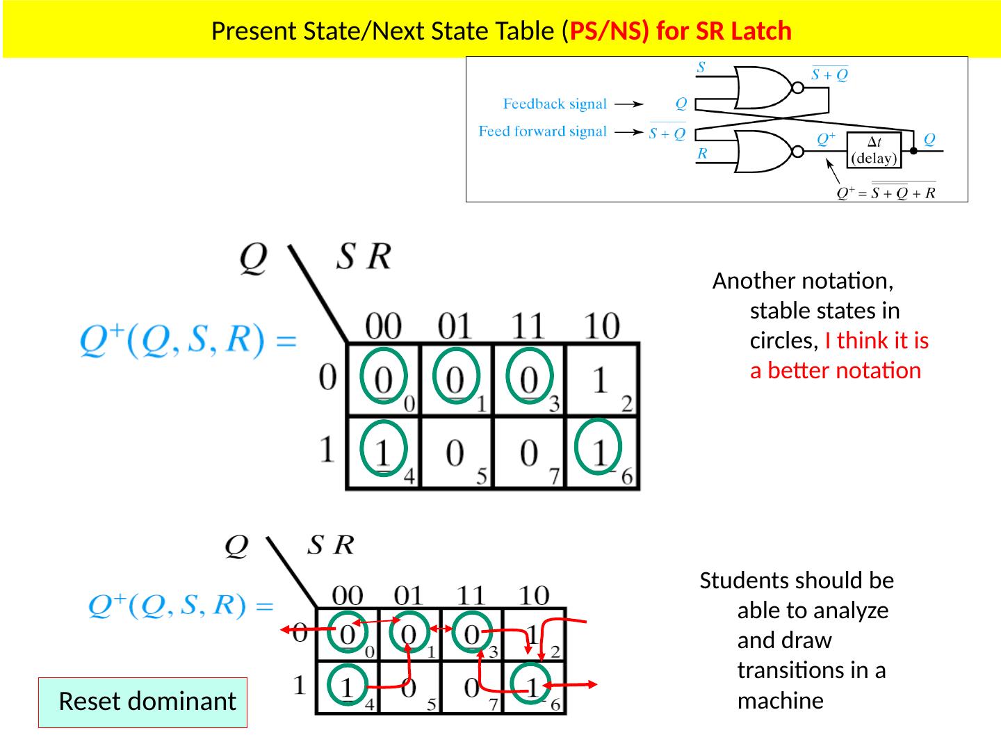
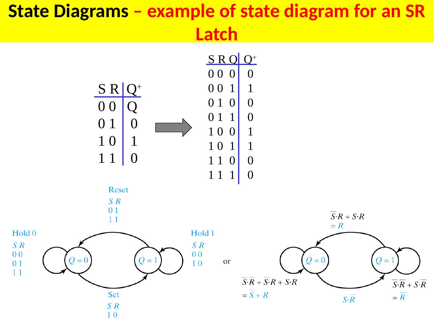
8 .Present State/Next State Table ( PS/NS) for SR Latch
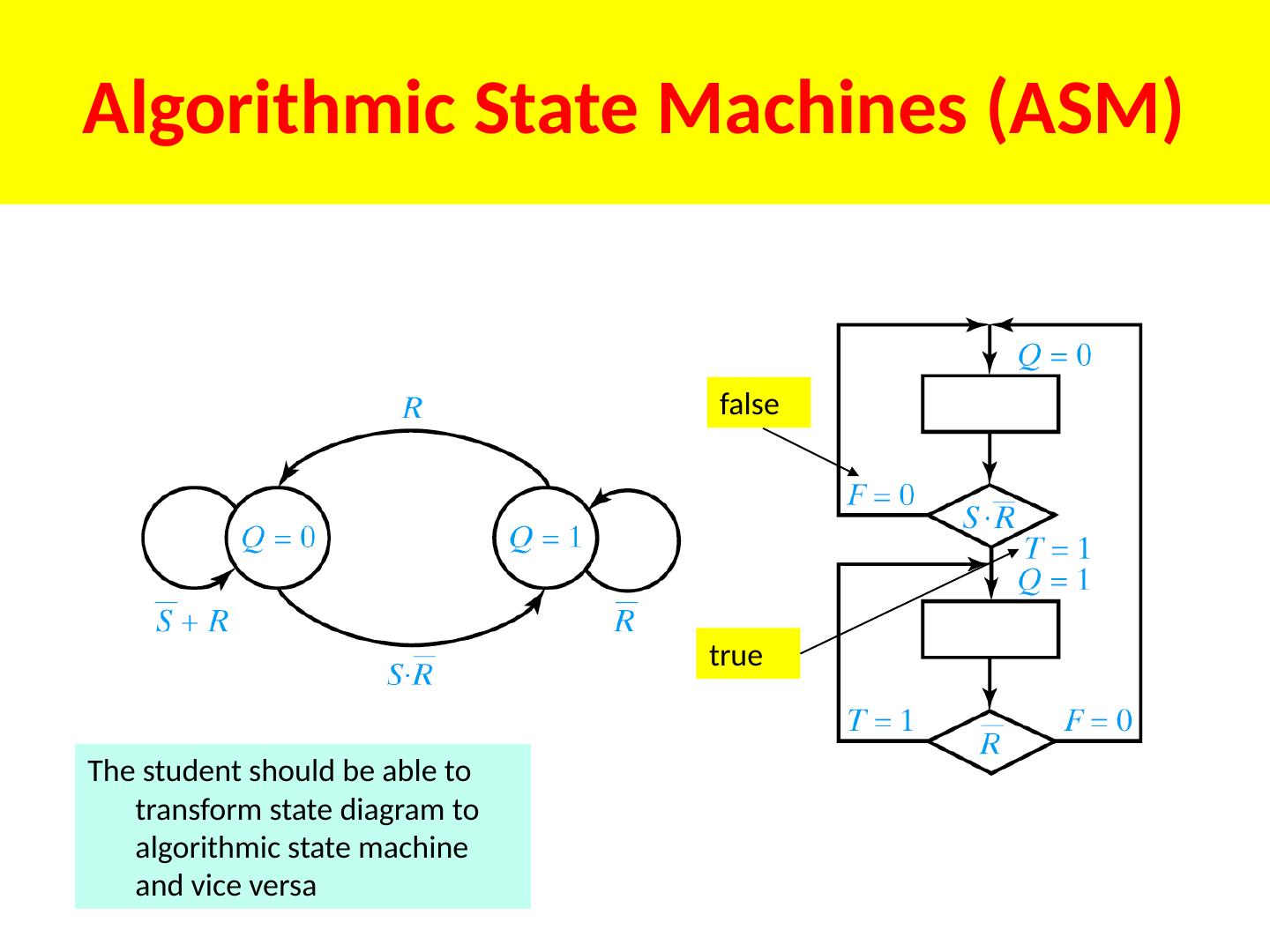
9 .Present State/Next State Table ( PS/NS) for SR Latch Another notation, stable states in circles, I think it is a better notation Students should be able to analyze and draw transitions in a machine Reset dominant
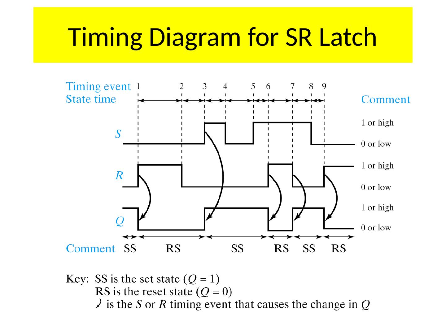
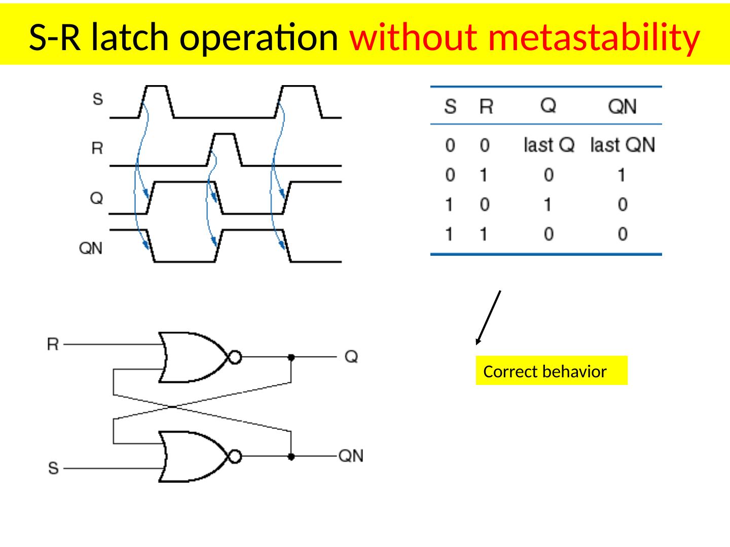
10 .Timing Diagram for SR Latch
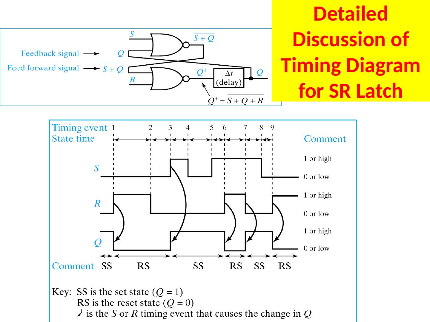
11 .Detailed Discussion of Timing Diagram for SR Latch
12 .Races Just as we used K-maps to not only reduce Boolean equations but to detect hazards, we can use K-maps to analyze anomalous latch behavior as well. Race is when two or more inputs change simultaneously. May or may not be a critical race. Depends upon the behavior of the circuit.
13 .Critical Races Can happen when two signals change at the same time
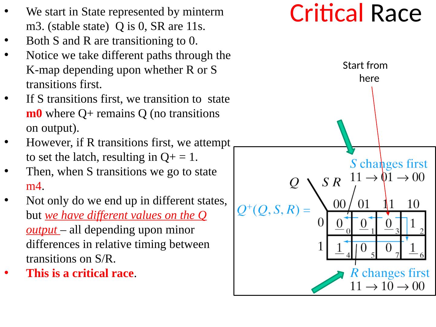
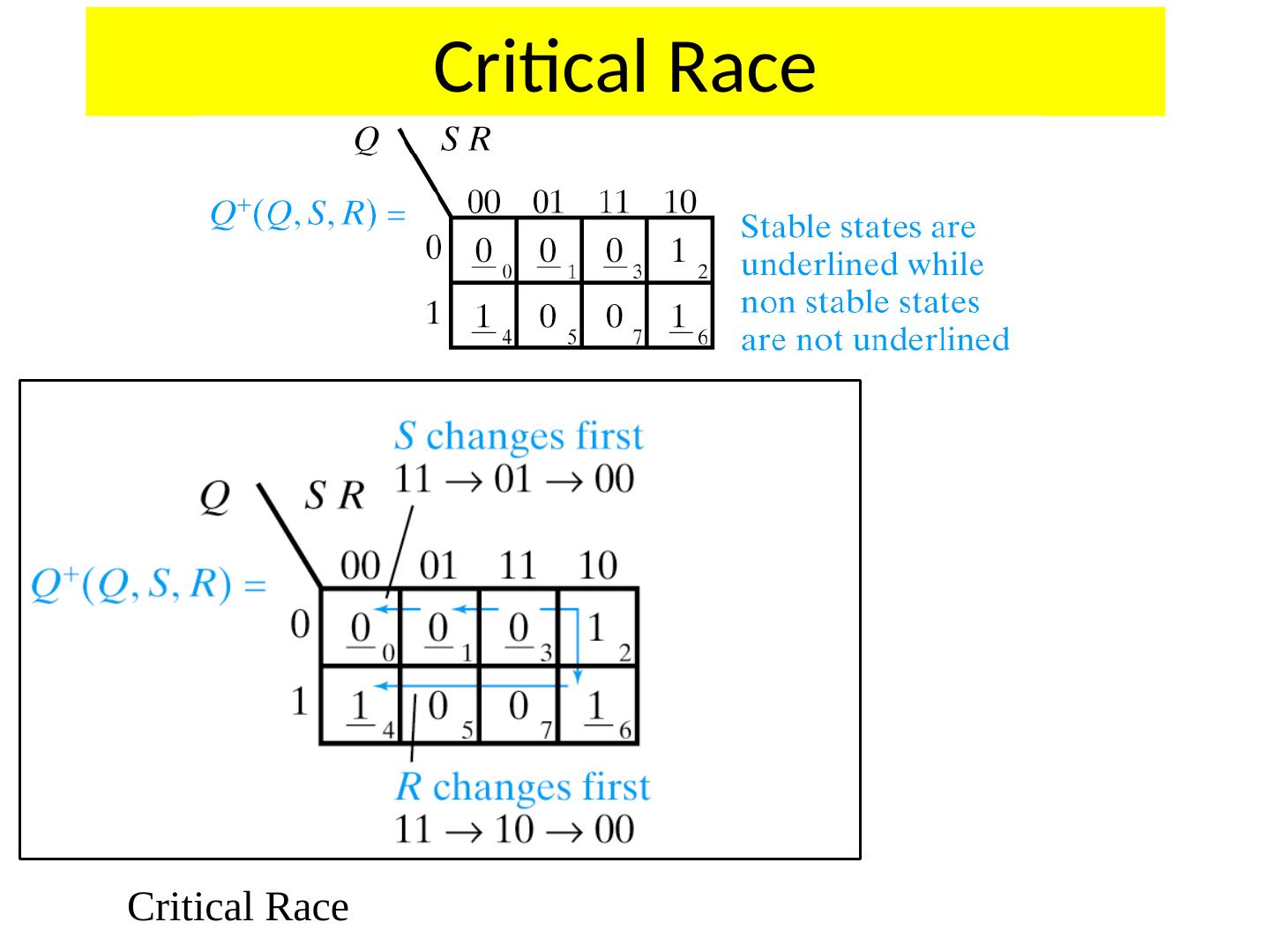
14 .Critical Race We start in State represented by minterm m3. (stable state) Q is 0, SR are 11s. Both S and R are transitioning to 0. Notice we take different paths through the K-map depending upon whether R or S transitions first. If S transitions first, we transition to state m0 where Q+ remains Q (no transitions on output). However , if R transitions first, we attempt to set the latch, resulting in Q+ = 1. Then , when S transitions we go to state m4 . Not only do we end up in different states, but we have different values on the Q output – all depending upon minor differences in relative timing between transitions on S/R. This is a critical race . Start from here
15 .Critical Race Critical Race
16 .Non-Critical Races
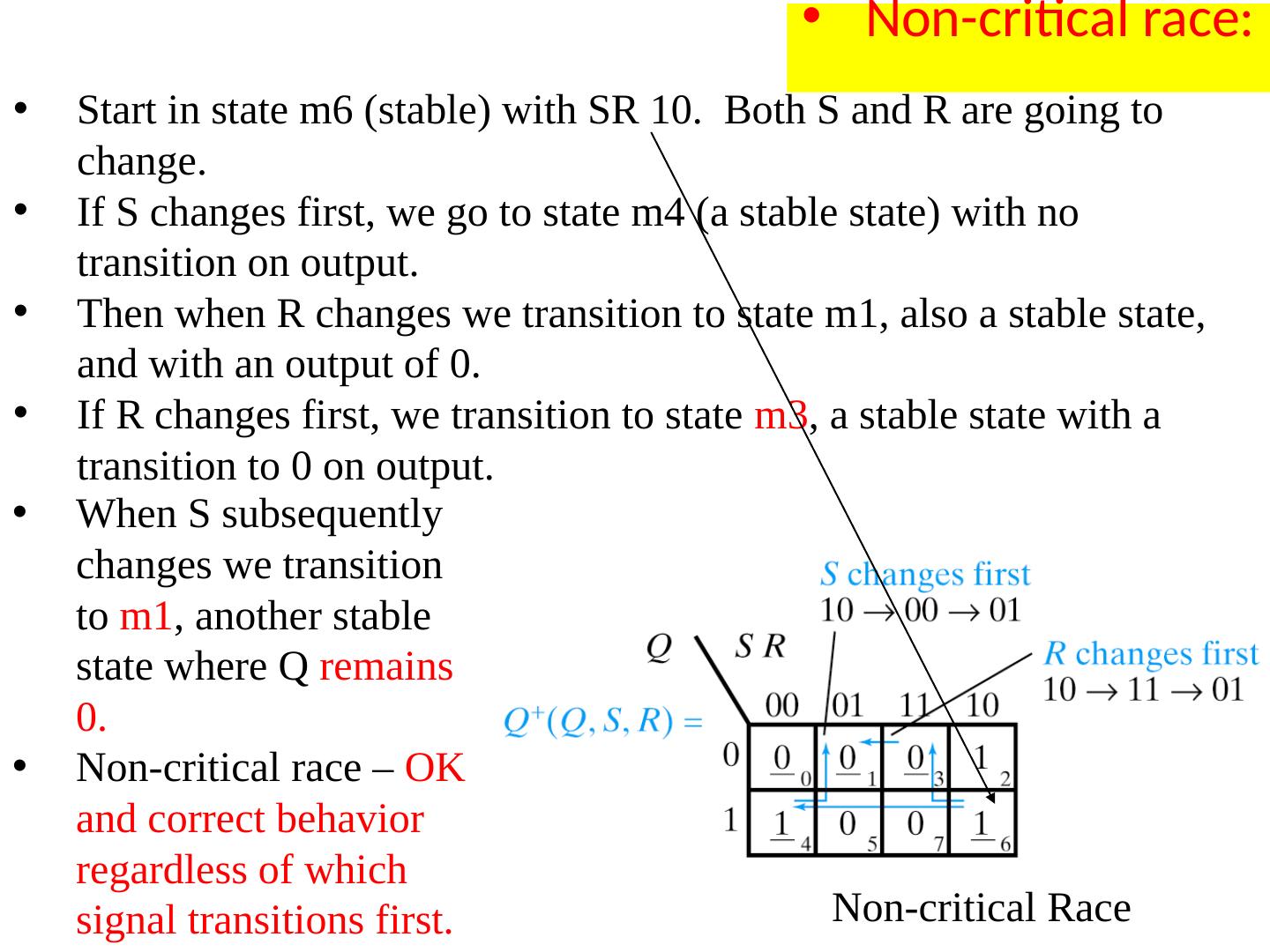
17 .Non-critical race: Start in state m6 (stable) with SR 10. Both S and R are going to change. If S changes first, we go to state m4 (a stable state) with no transition on output. Then when R changes we transition to state m1, also a stable state, and with an output of 0. If R changes first, we transition to state m3 , a stable state with a transition to 0 on output. When S subsequently changes we transition to m1 , another stable state where Q remains 0. Non-critical race – OK and correct behavior regardless of which signal transitions first. Non-critical Race
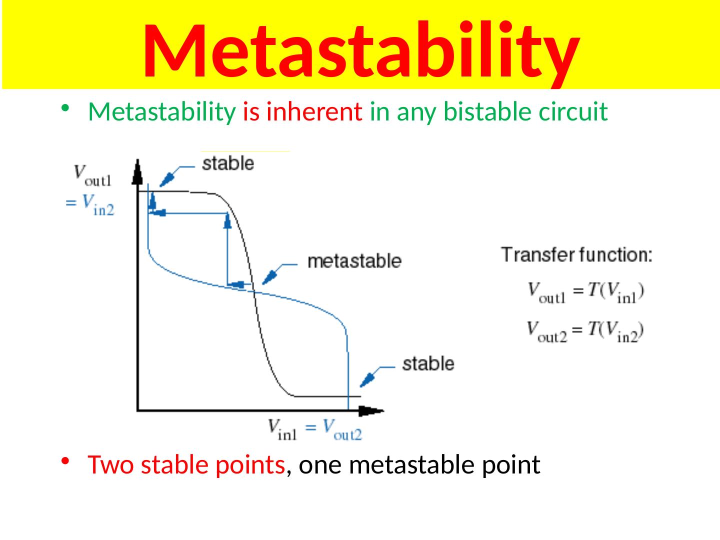
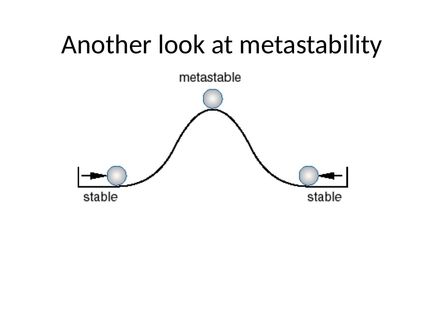
18 .Metastable State
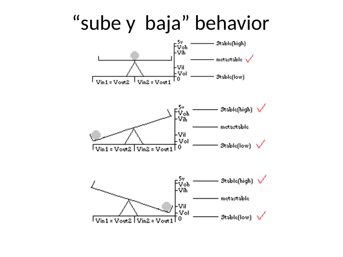
19 .Metastable State An often overlooked condition in which the output can remain in an illegal (even oscillating) state for an indeterminant period of time. Metastability can be caused by a runt pulse (a positive or negative pulse which never achieves either a value of a 1 or 0). This can occur when two inputs to a gate change near simultaneously (see hazards earlier). Metastability can also occur when two inputs to a latch change near simultaneously. Condition also arises when synchronizing with external events (e.g. asynchronous inputs to synchronous finite state machines).
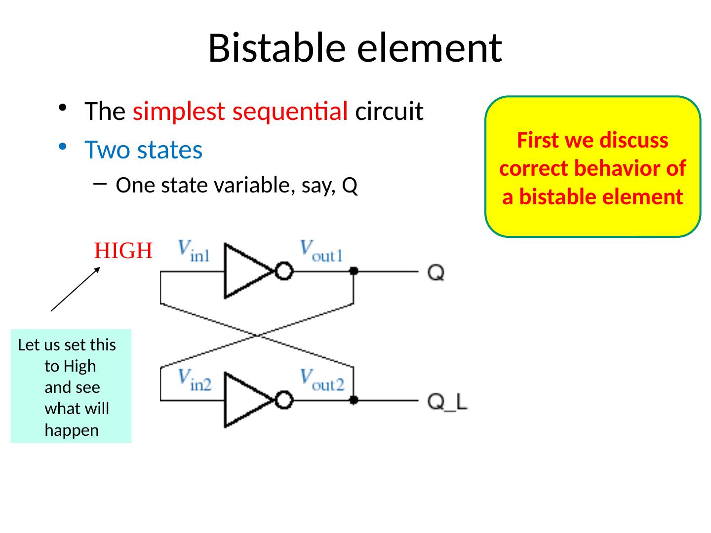
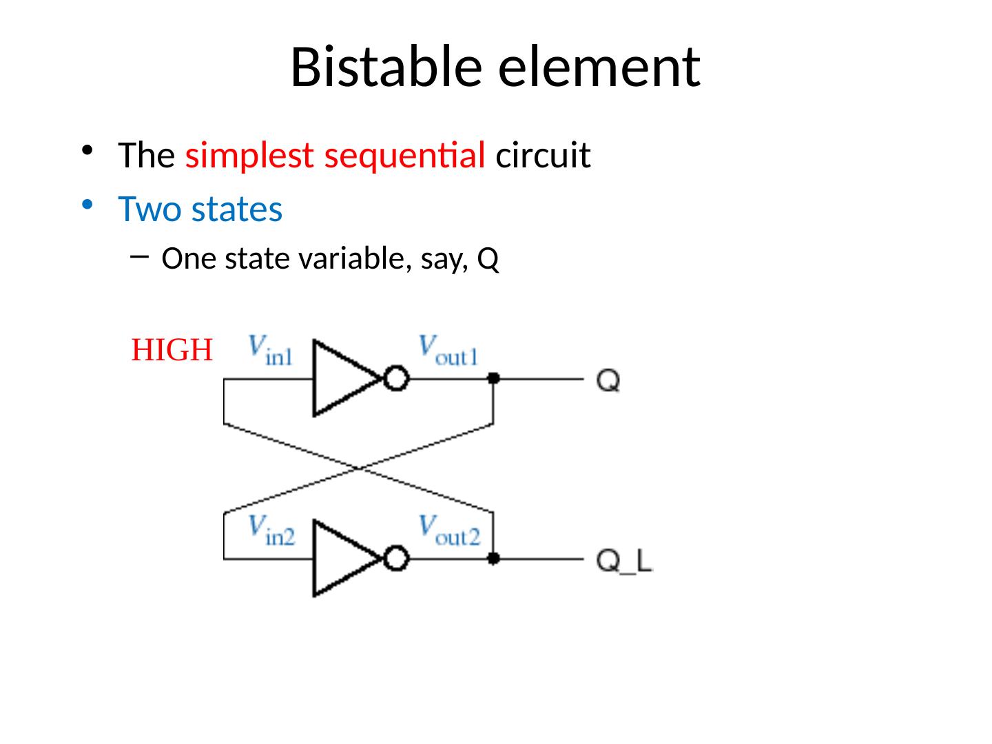
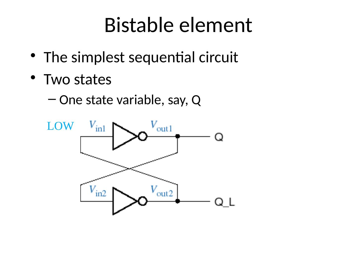
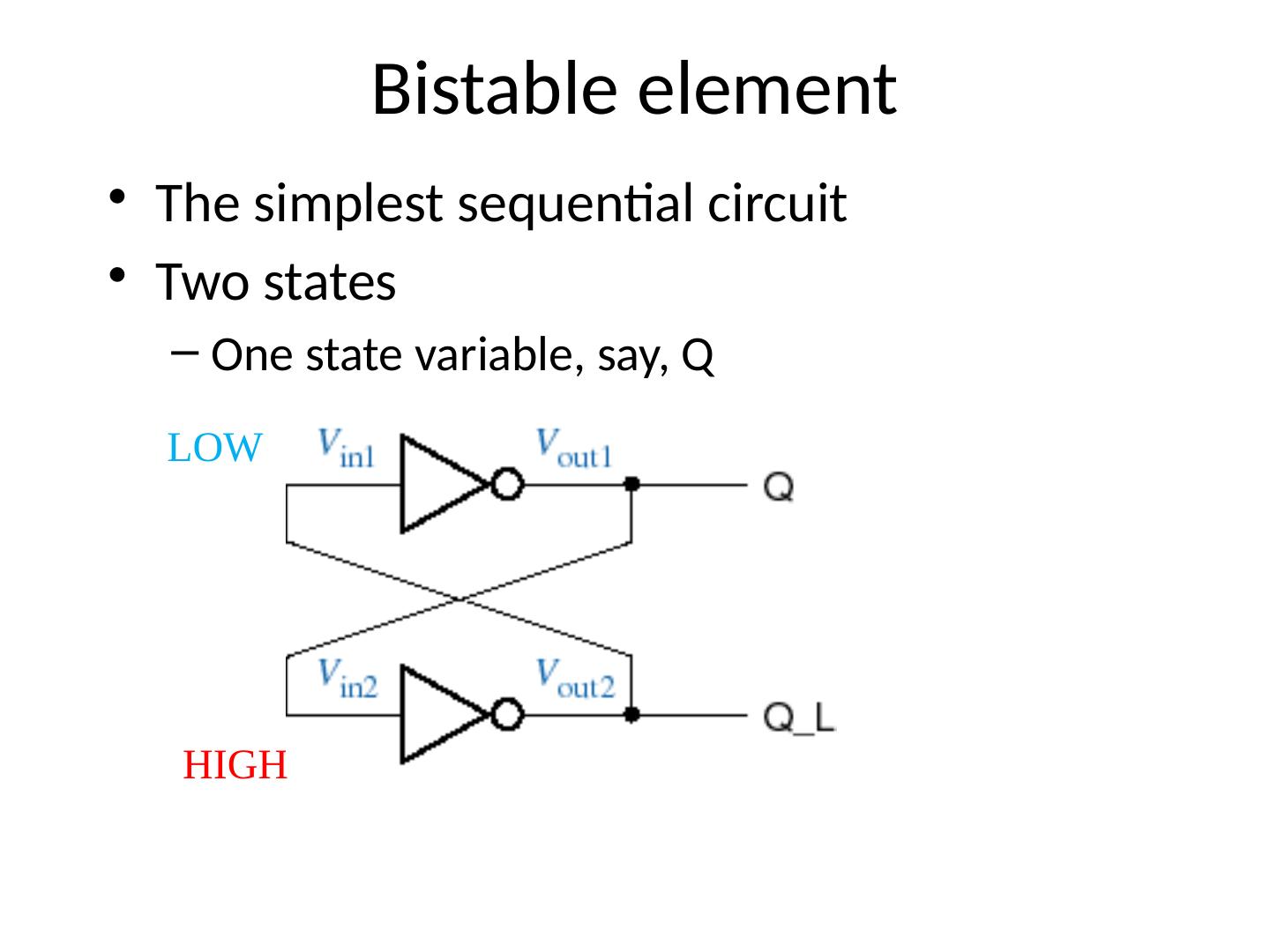
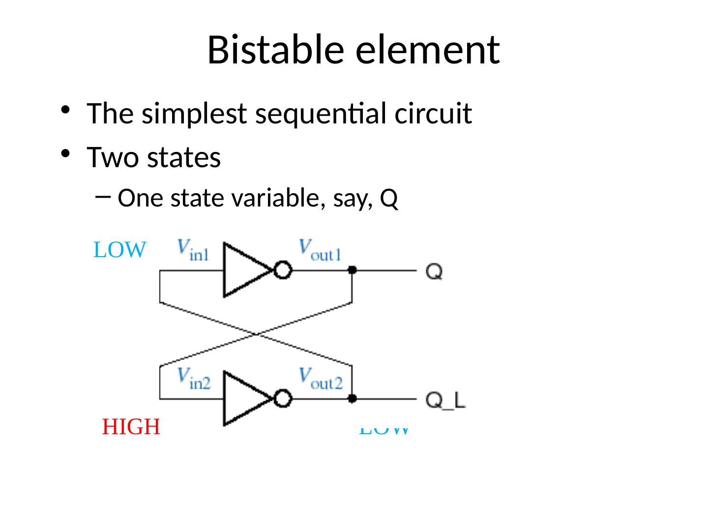
20 .Bistable element The simplest sequential circuit Two states One state variable, say, Q HIGH Let us set this to High and see what will happen First we discuss correct behavior of a bistable element
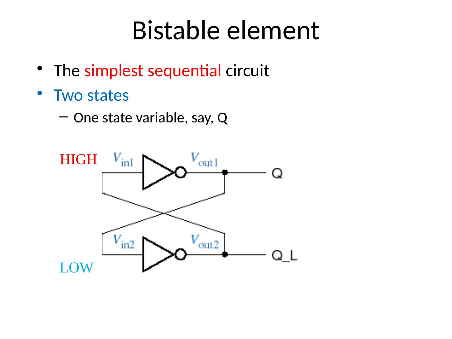
21 .Bistable element The simplest sequential circuit Two states One state variable, say, Q HIGH LOW
22 .Bistable element The simplest sequential circuit Two states One state variable, say, Q HIGH LOW LOW
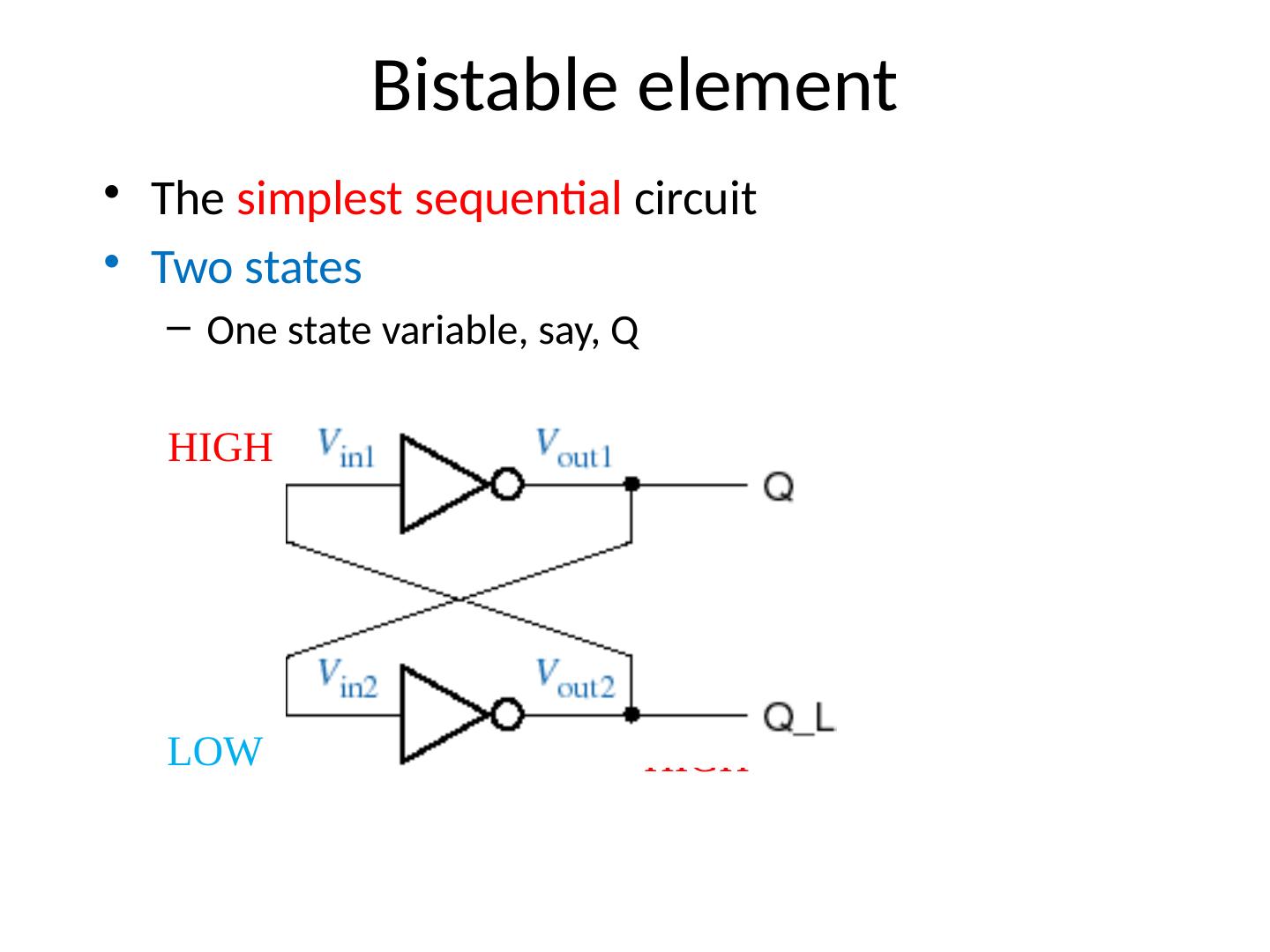
23 .Bistable element The simplest sequential circuit Two states One state variable, say, Q HIGH LOW LOW HIGH
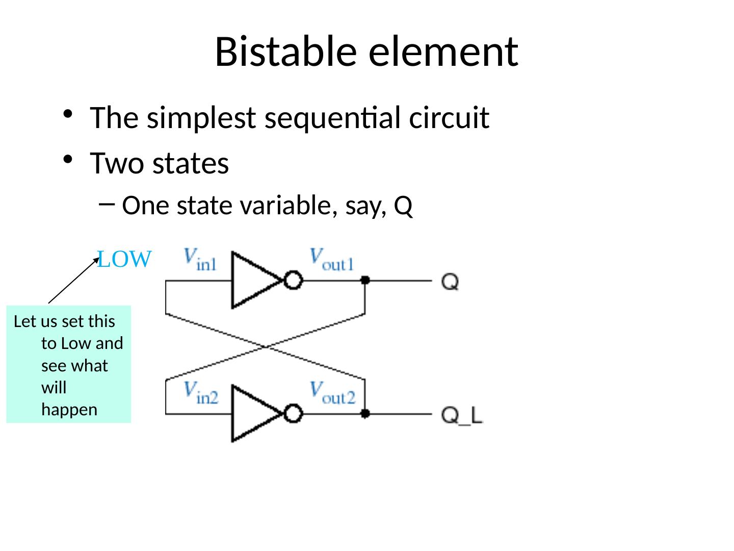
24 .Bistable element The simplest sequential circuit Two states One state variable, say, Q LOW Let us set this to Low and see what will happen
25 .Bistable element The simplest sequential circuit Two states One state variable, say, Q LOW HIGH
26 .Bistable element The simplest sequential circuit Two states One state variable, say, Q LOW HIGH HIGH
27 .Bistable element The simplest sequential circuit Two states One state variable, say, Q LOW HIGH HIGH LOW
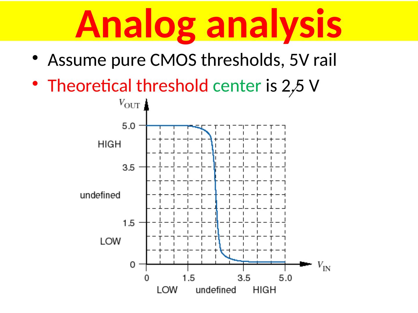
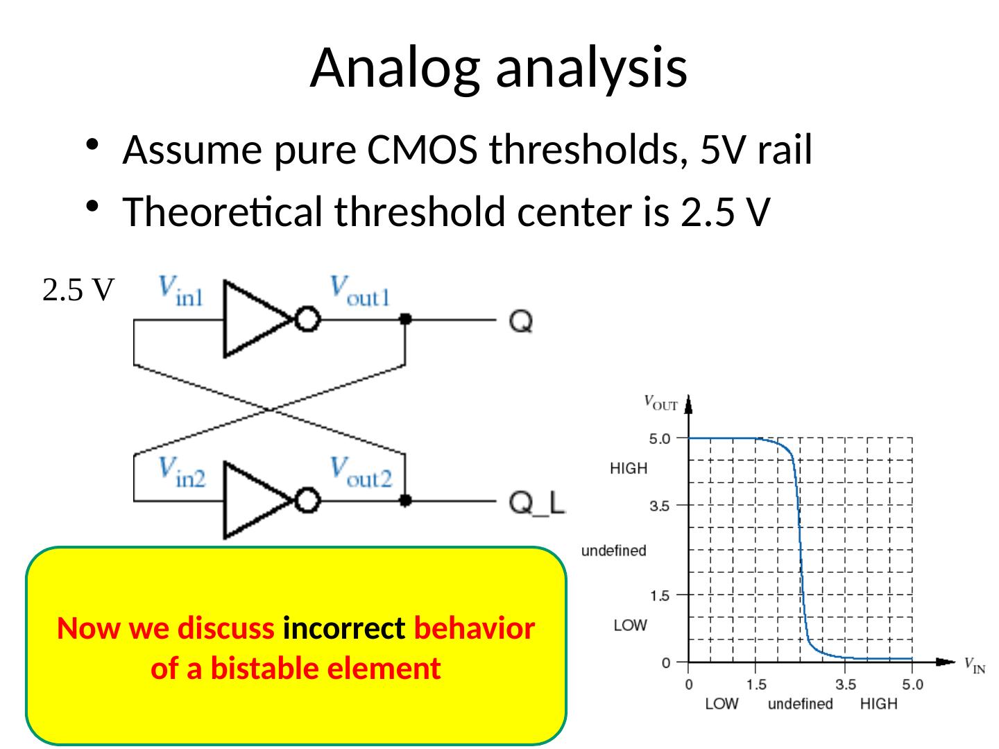
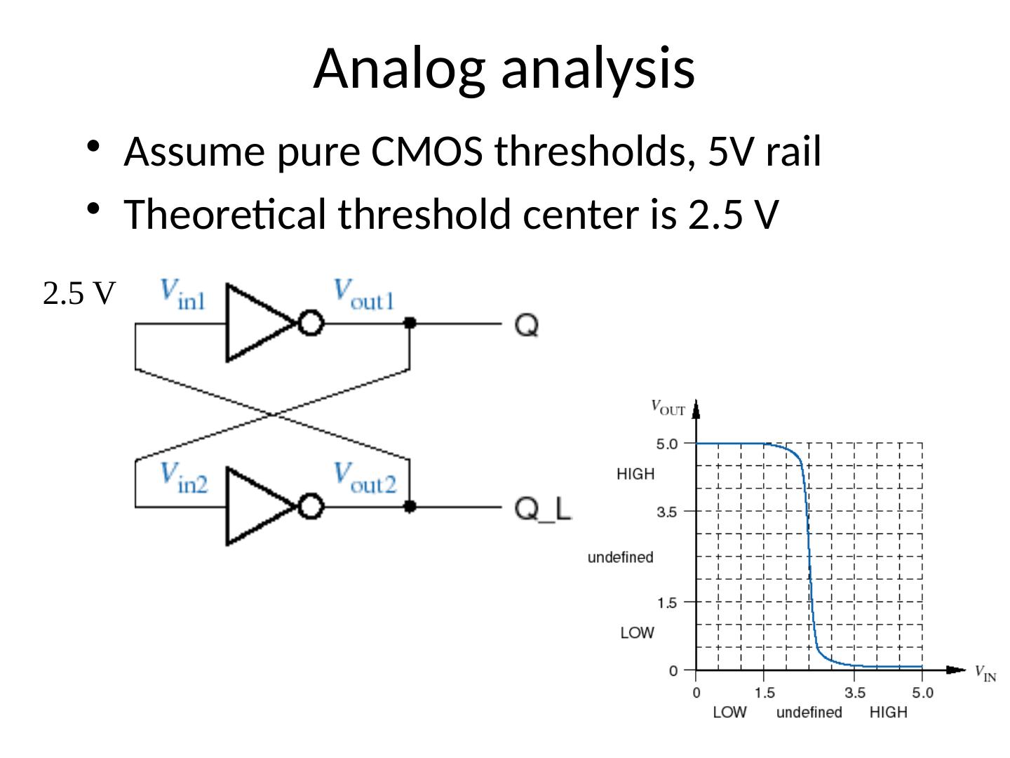
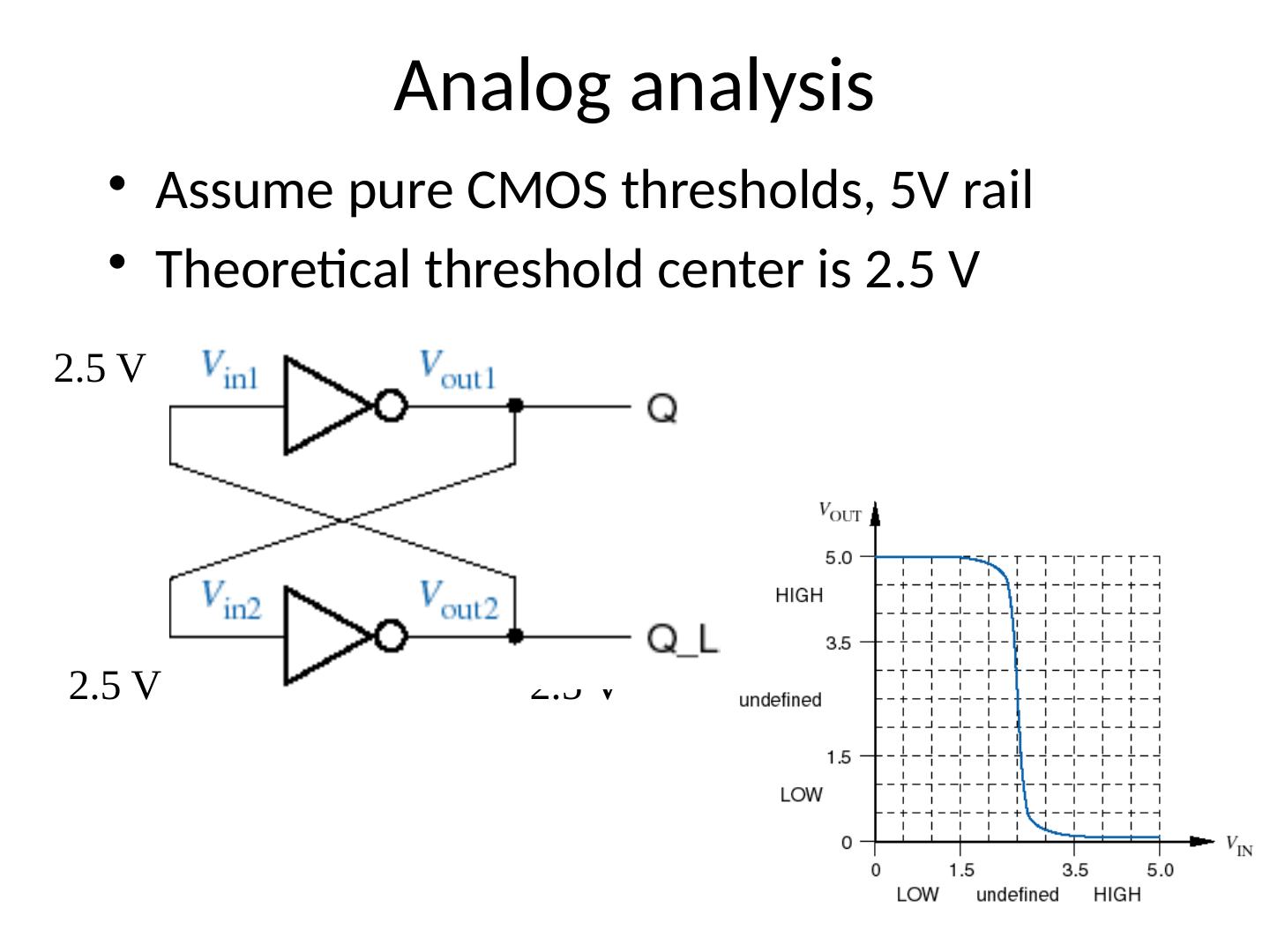
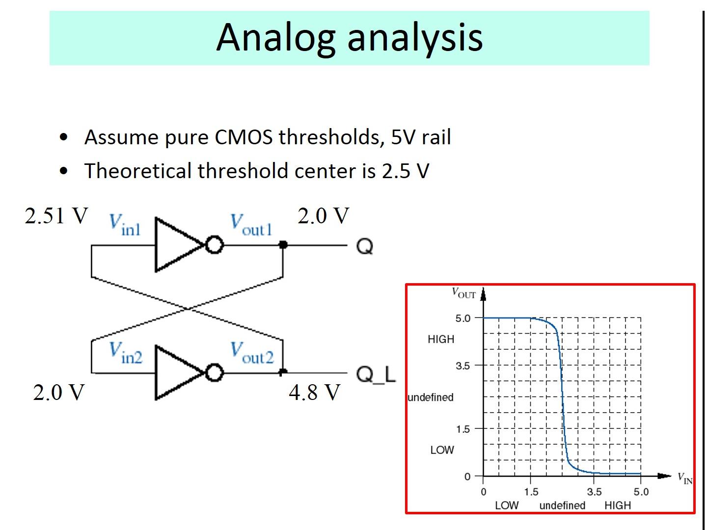
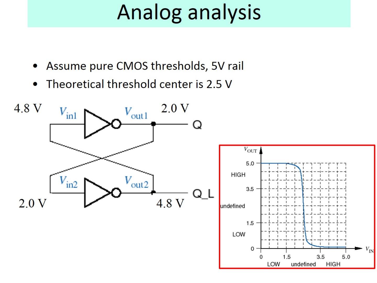
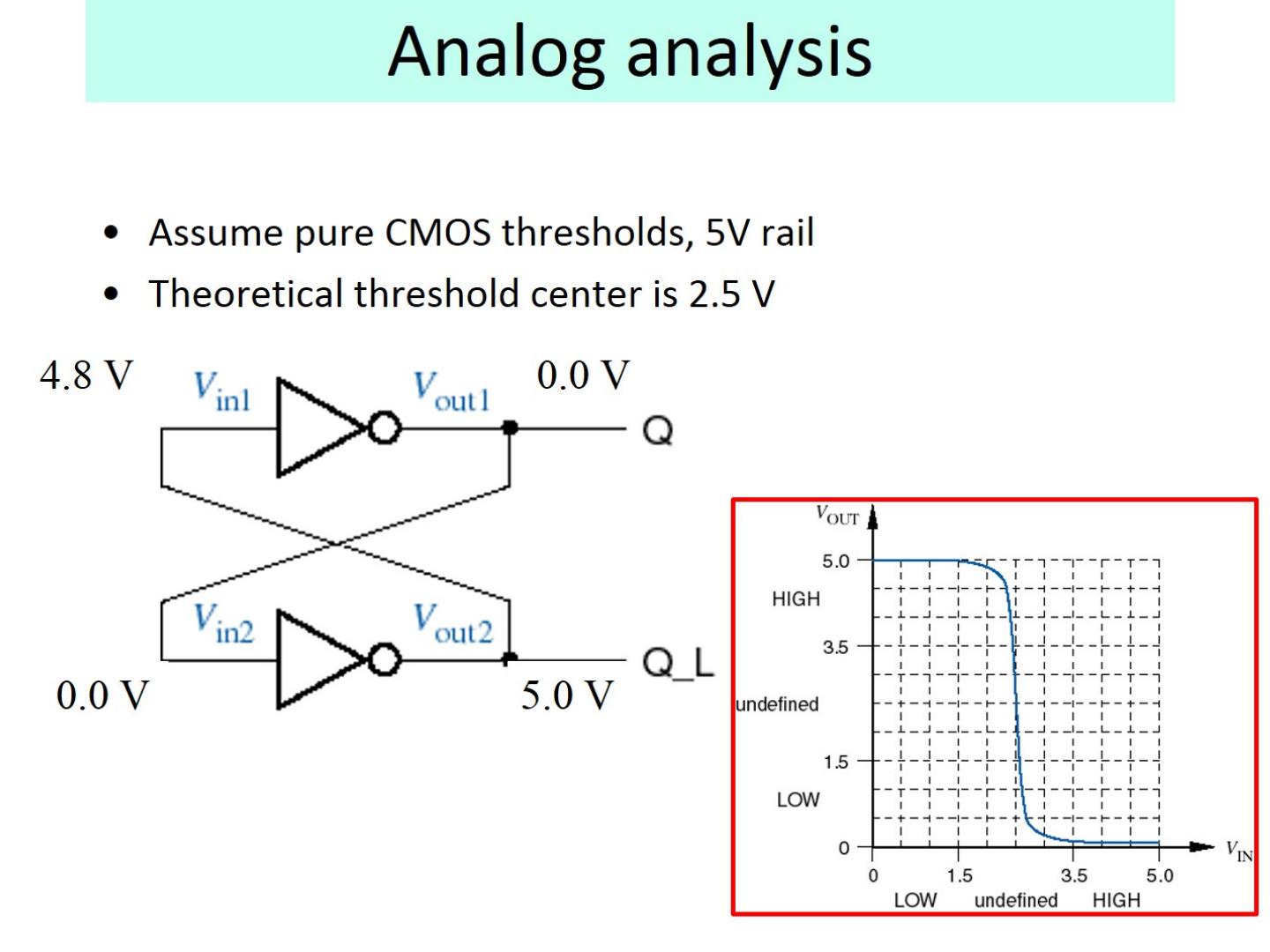
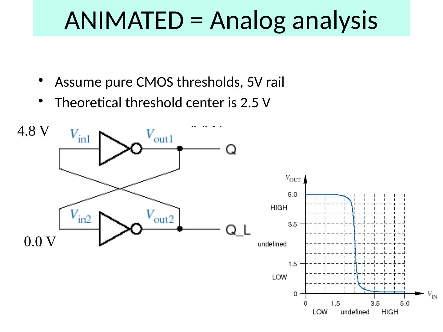
28 .Analog analysis Assume pure CMOS thresholds, 5V rail Theoretical threshold center is 2.5 V
29 .Analog analysis Assume pure CMOS thresholds, 5V rail Theoretical threshold center is 2.5 V 2.5 V Now we discuss incorrect behavior of a bistable element


