


- 快召唤伙伴们来围观吧
- 微博 QQ QQ空间 贴吧
- 文档嵌入链接
- 复制
- 微信扫一扫分享
- 已成功复制到剪贴板
08 Arduino- lecture_microcontroller_overview
Explain the general architecture of a microcontroller
List the key features of the ATmega328 microcontroller
Explain the features and elements of the Arduino and Spartronics Experimenter Shield (SES)
Explain the concepts of microcontroller pins as inputs and outputs
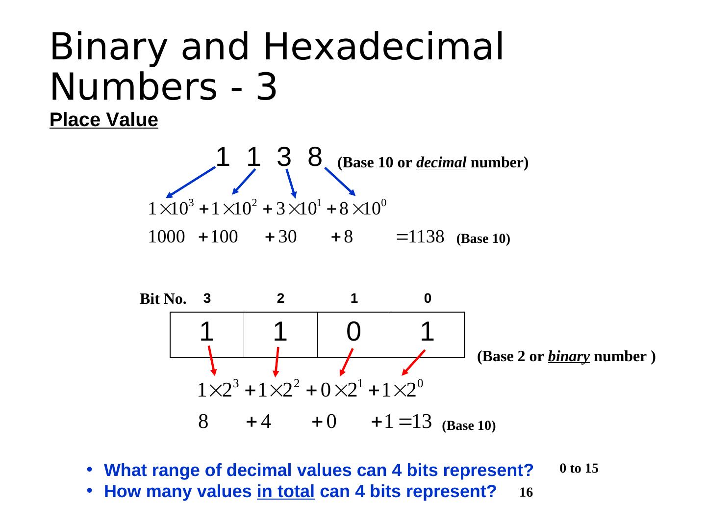
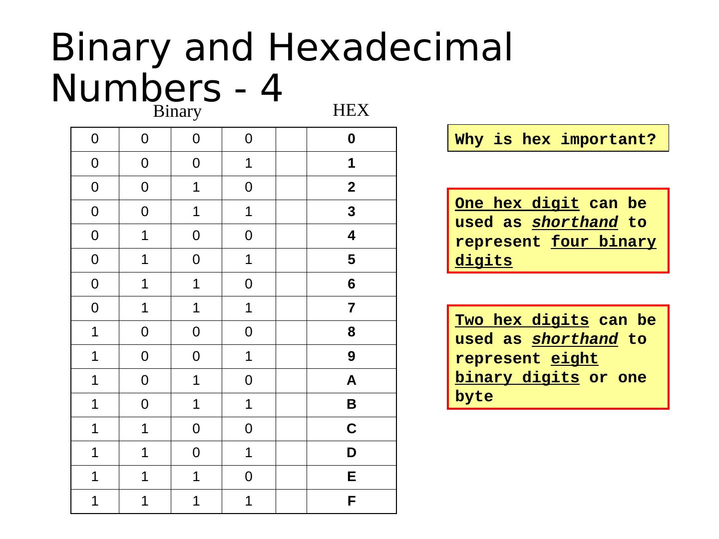
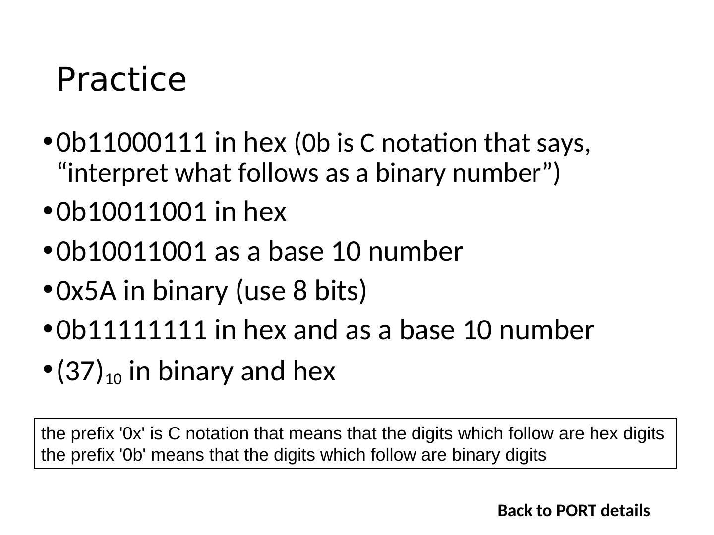
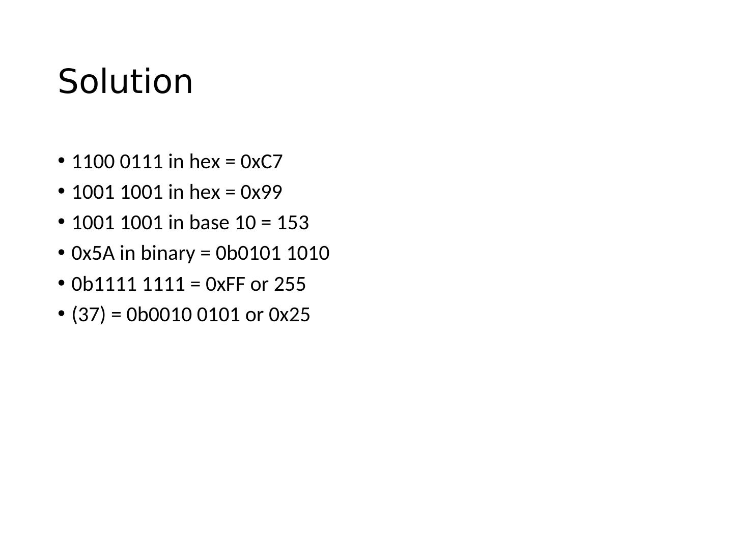
Convert between binary and hexadecimal digits
展开查看详情
1 . Learning Objectives • Explain the general architecture of a microcontroller • List the key features of the ATmega328 microcontroller • Explain the features and elements of the Arduino and Spartronics Experimenter Shield (SES) • Explain the concepts of microcontroller pins as inputs and outputs • Convert between binary and hexadecimal digits
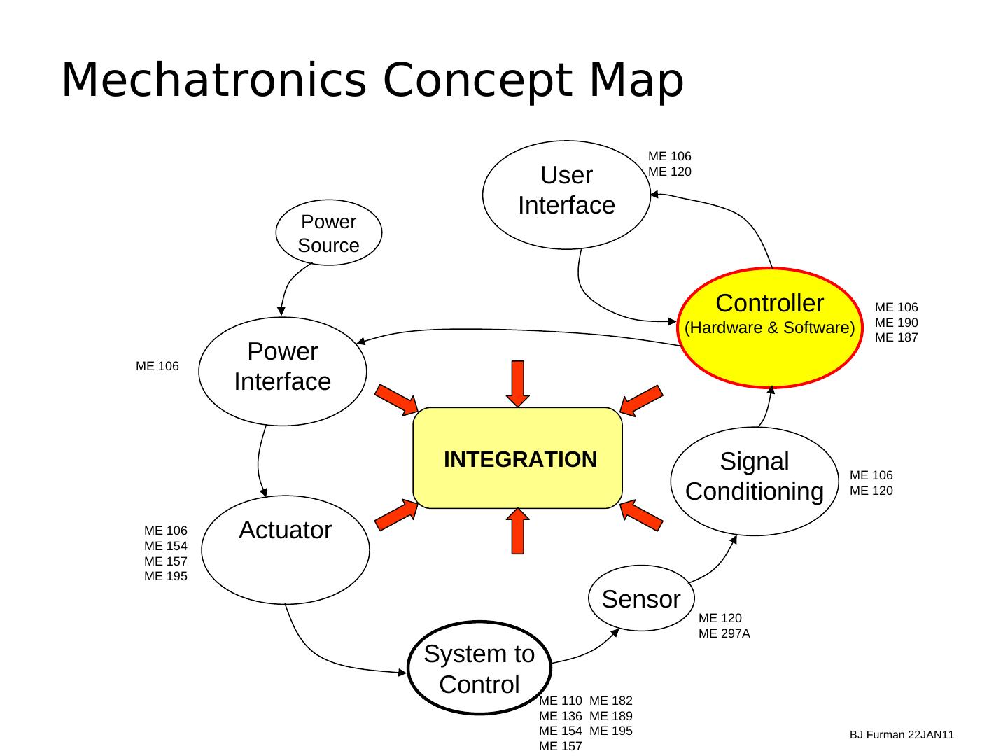
2 .Mechatronics Concept Map ME 106 User ME 120 Interface Power Source Controller ME 106 ME 190 (Hardware & Software) ME 187 ME 106 Power Interface INTEGRATION Signal ME 106 Conditioning ME 120 ME 106 ME 154 Actuator ME 157 ME 195 Sensor ME 120 ME 297A System to Control ME 110 ME 182 ME 136 ME 189 ME 154 ME 195 BJ Furman 22JAN11 ME 157
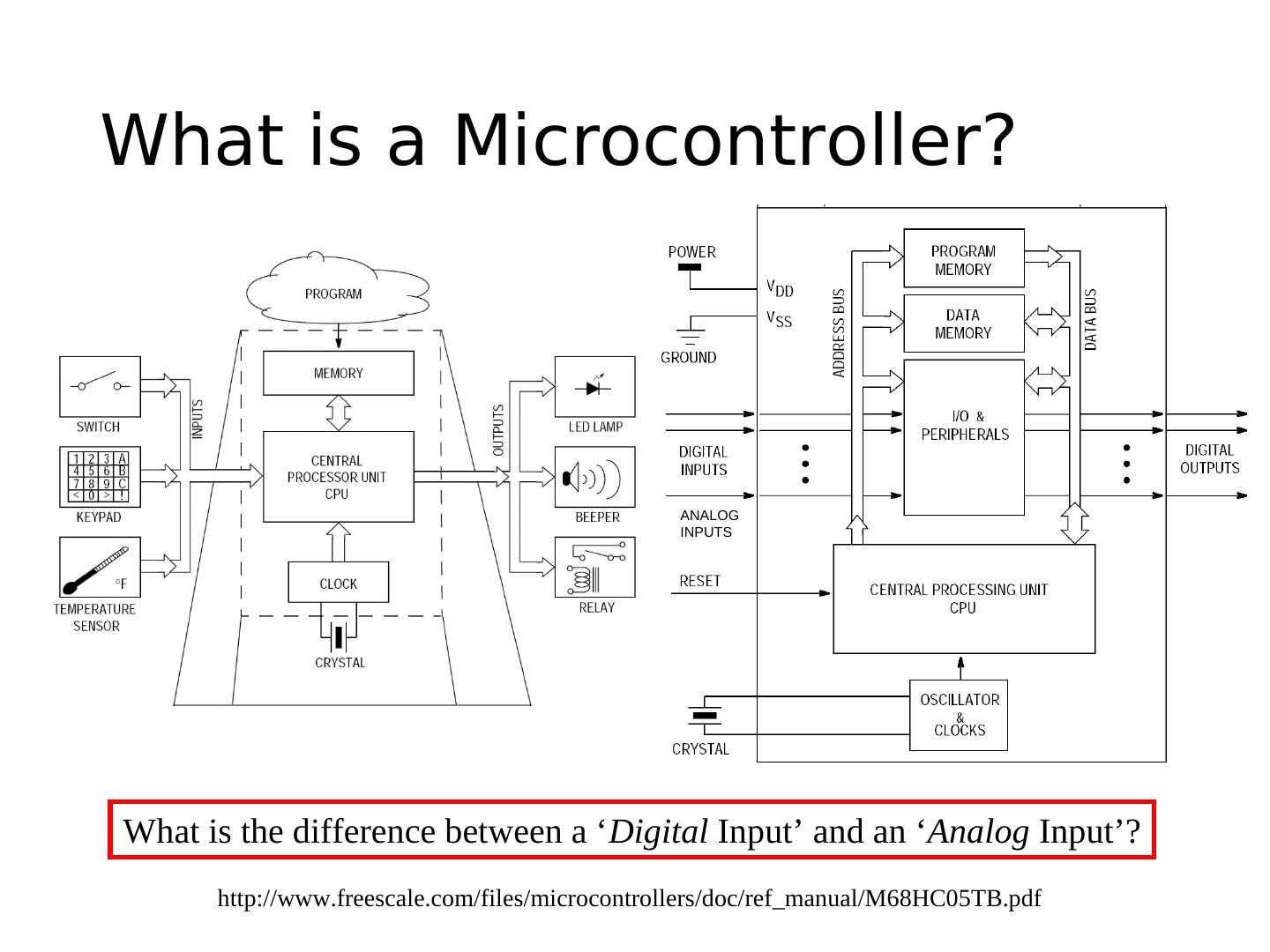
3 .What is a Microcontroller? ANALOG INPUTS What is the difference between a ‘Digital Input’ and an ‘Analog Input’? http://www.freescale.com/files/microcontrollers/doc/ref_manual/M68HC05TB.pdf
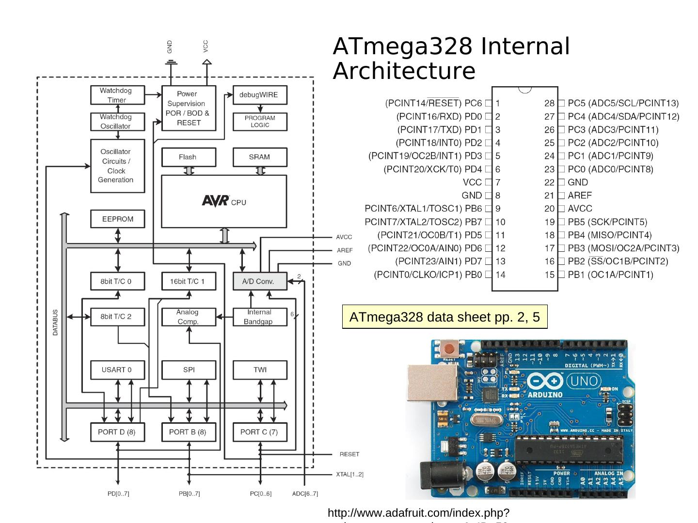
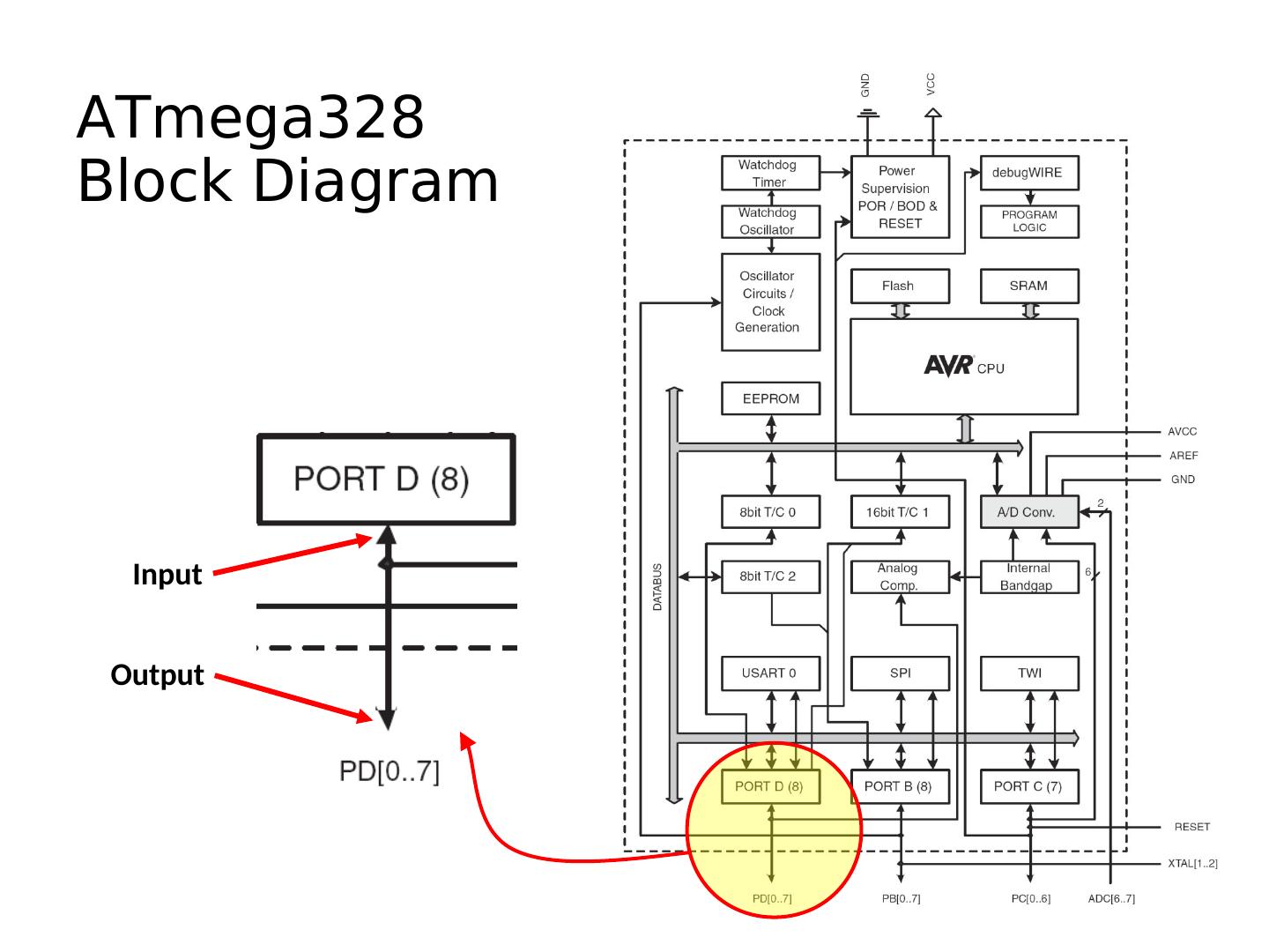
4 .ATmega328 Internal Architecture ATmega328 data sheet pp. 2, 5 http://www.adafruit.com/index.php?
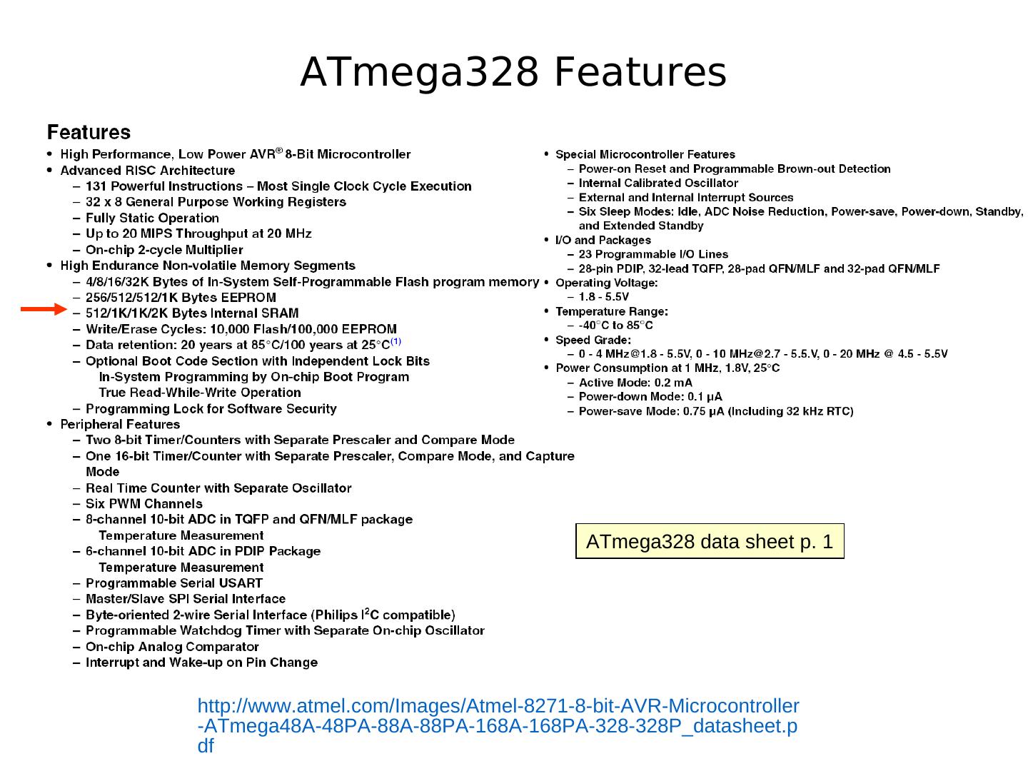
5 . ATmega328 Features ATmega328 data sheet p. 1 http://www.atmel.com/Images/Atmel-8271-8-bit-AVR-Microcontroller -ATmega48A-48PA-88A-88PA-168A-168PA-328-328P_datasheet.p df
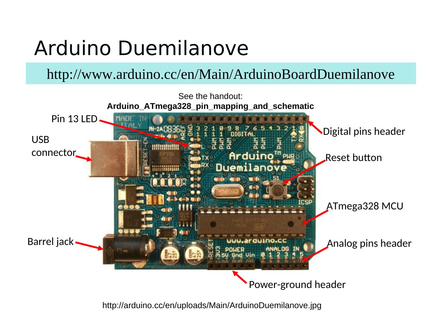
6 . Arduino Duemilanove http://www.arduino.cc/en/Main/ArduinoBoardDuemilanove See the handout: Arduino_ATmega328_pin_mapping_and_schematic Pin 13 LED Digital pins header USB connector Reset button ATmega328 MCU Barrel jack Analog pins header Power-ground header http://arduino.cc/en/uploads/Main/ArduinoDuemilanove.jpg
7 . Arduino Uno R3 ATmega16u2 replaces FT232RL for USB-serial communication http://www.adafruit.com/index.php? main_page=popup_image&pID=50 See: http://learn.adafruit.com/arduino-tips-tricks-and-techniques/arduino-uno-faq
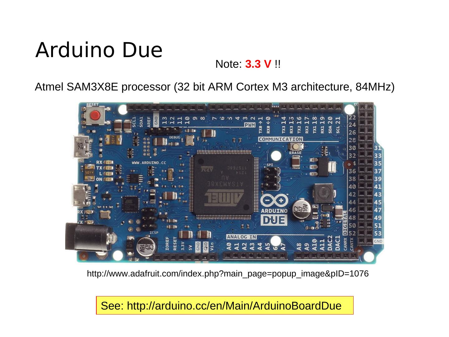
8 .Arduino Due Note: 3.3 V !! Atmel SAM3X8E processor (32 bit ARM Cortex M3 architecture, 84MHz) http://www.adafruit.com/index.php?main_page=popup_image&pID=1076 See: http://arduino.cc/en/Main/ArduinoBoardDue
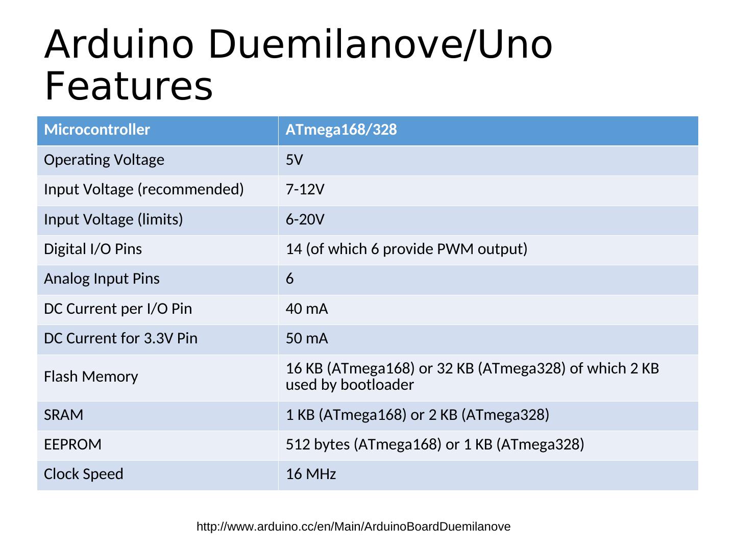
9 .Arduino Duemilanove/Uno Features Microcontroller ATmega168/328 Operating Voltage 5V Input Voltage (recommended) 7-12V Input Voltage (limits) 6-20V Digital I/O Pins 14 (of which 6 provide PWM output) Analog Input Pins 6 DC Current per I/O Pin 40 mA DC Current for 3.3V Pin 50 mA 16 KB (ATmega168) or 32 KB (ATmega328) of which 2 KB Flash Memory used by bootloader SRAM 1 KB (ATmega168) or 2 KB (ATmega328) EEPROM 512 bytes (ATmega168) or 1 KB (ATmega328) Clock Speed 16 MHz http://www.arduino.cc/en/Main/ArduinoBoardDuemilanove
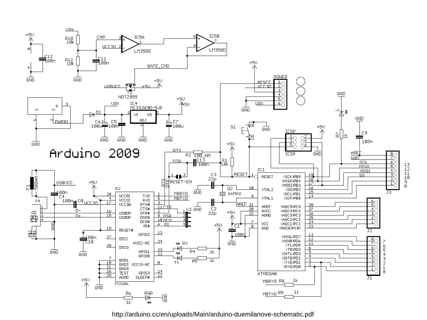
10 .http://arduino.cc/en/uploads/Main/arduino-duemilanove-schematic.pdf
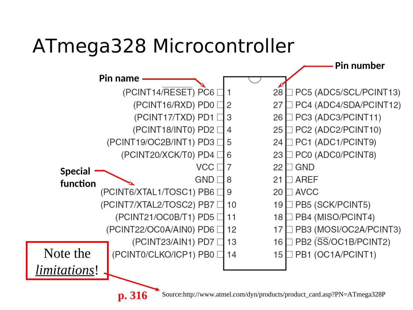
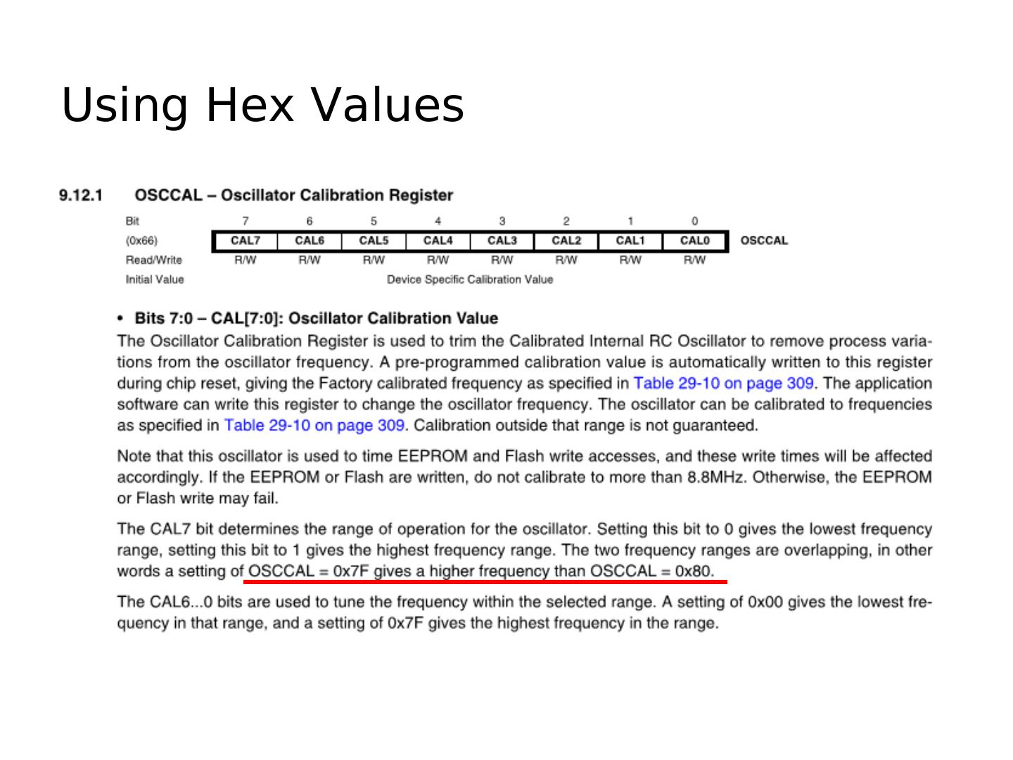
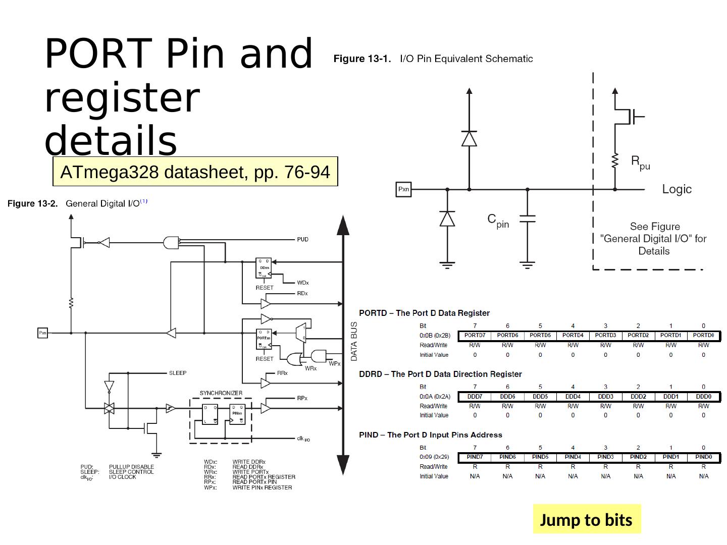
11 .ATmega328 Microcontroller Pin number Pin name Special function Note the limitations! p. 316 Source:http://www.atmel.com/dyn/products/product_card.asp?PN=ATmega328P
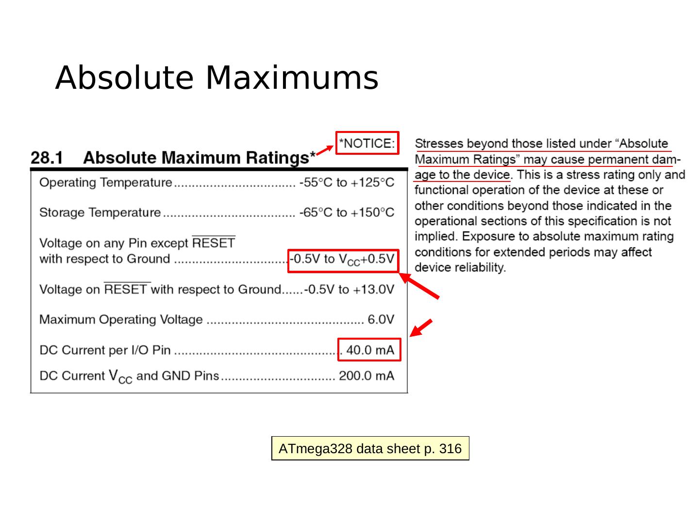
12 .Absolute Maximums ATmega328 data sheet p. 316
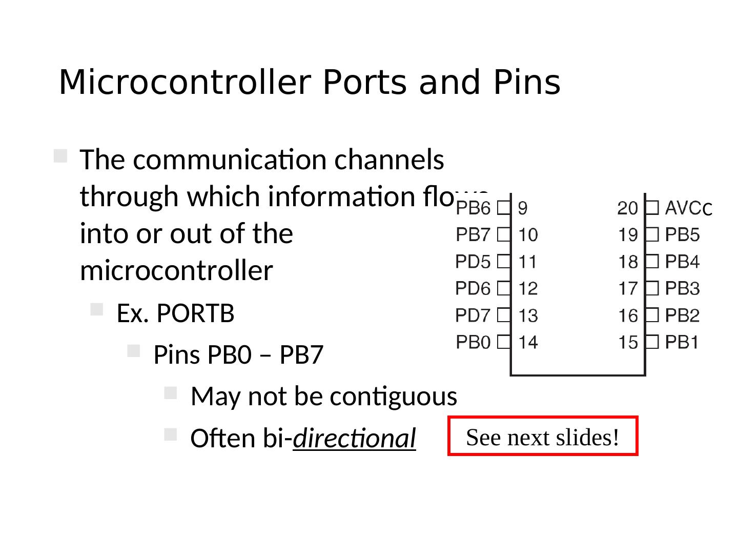
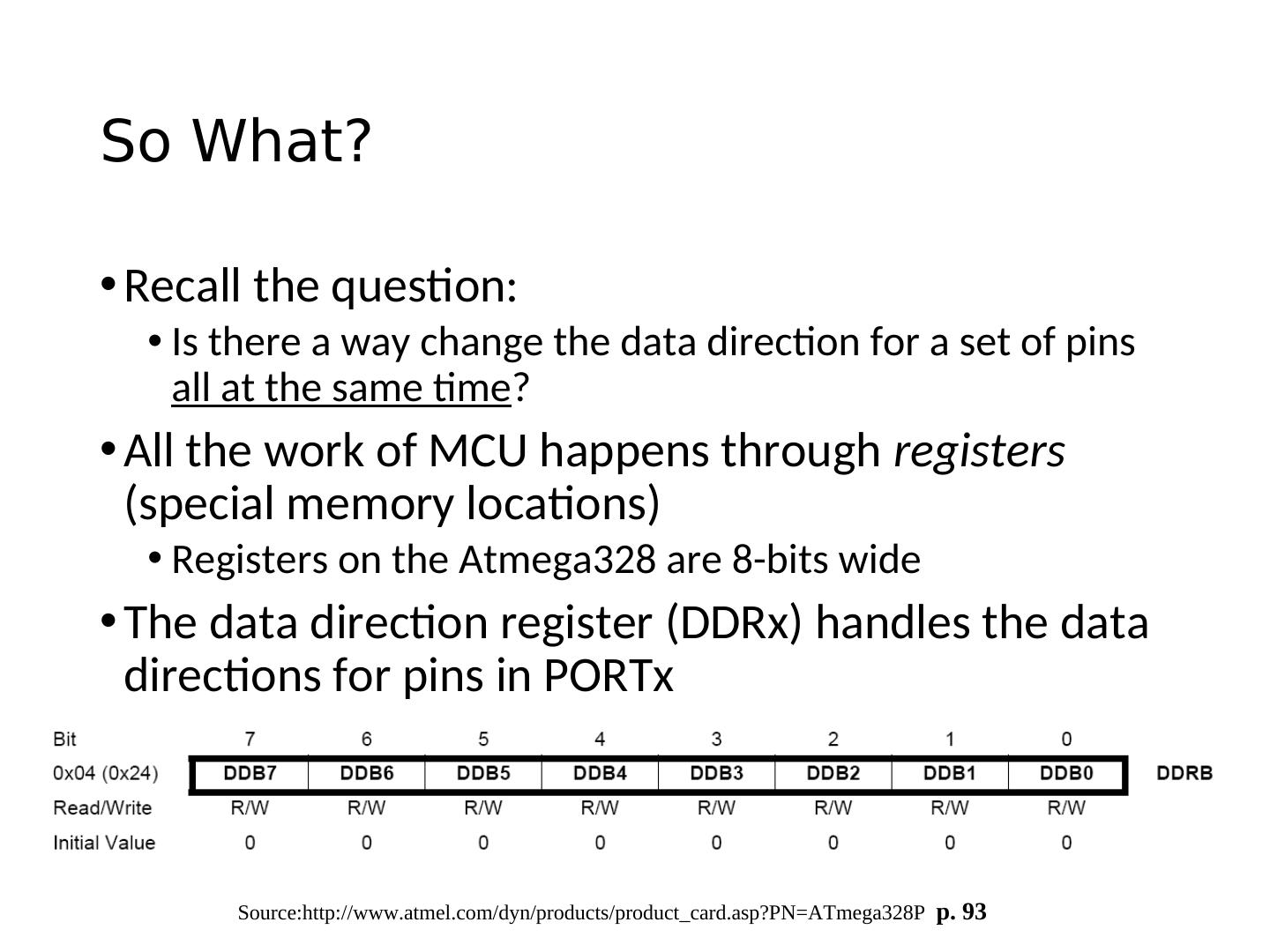
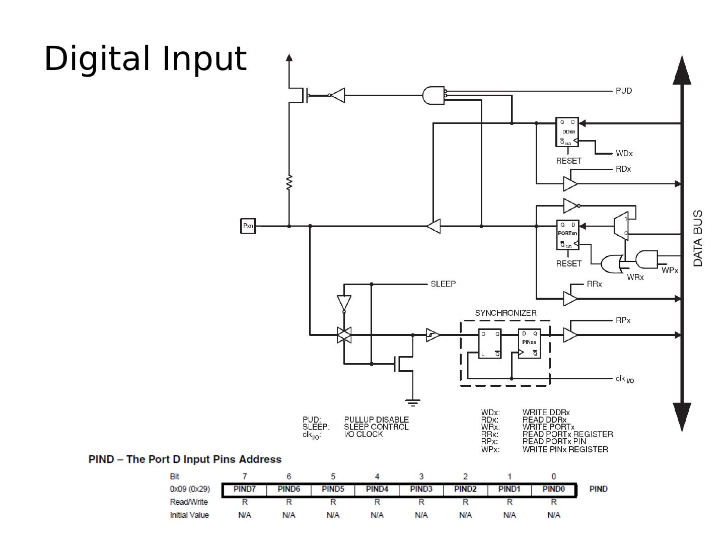
13 .Microcontroller Ports and Pins The communication channels through which information flows C into or out of the microcontroller Ex. PORTB Pins PB0 – PB7 May not be contiguous Often bi-directional See next slides!
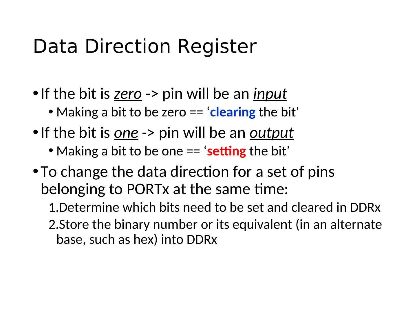
14 .Port Pin Data Directionality • Input • When you want to take information from the external world (sensors) into the MCU • Output • When you want to change the state of something outside the MCU (turn a motor on or off, etc.) • Pins default to input direction on power-up or reset • Your program can set or change the directionality of a pin at any time
15 .ATmega328 Block Diagram Input Output
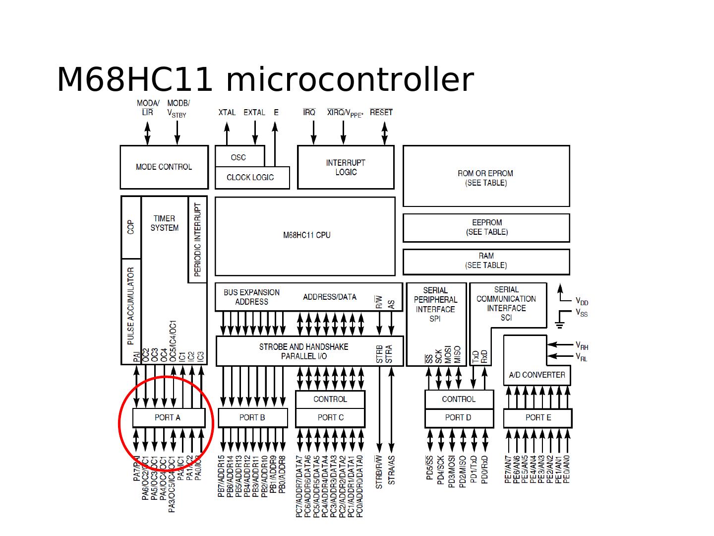
16 .M68HC11 microcontroller
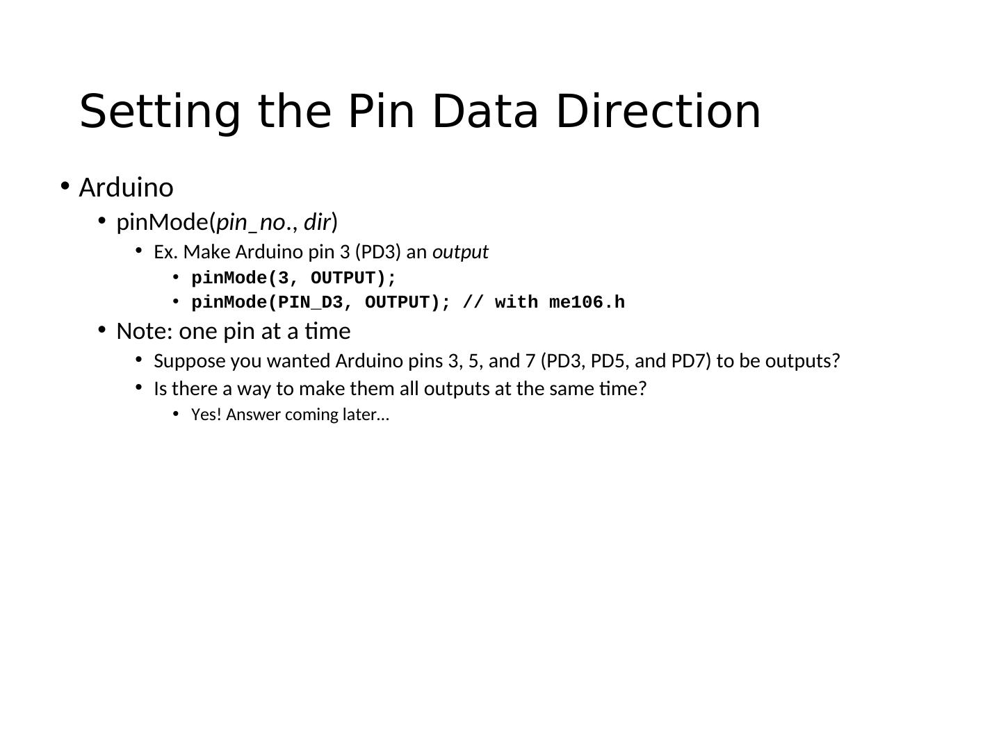
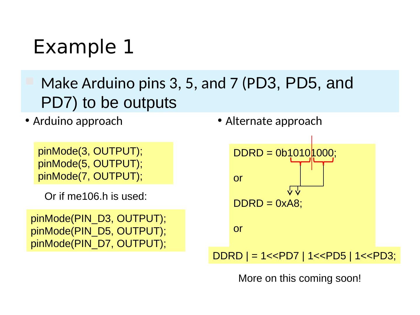
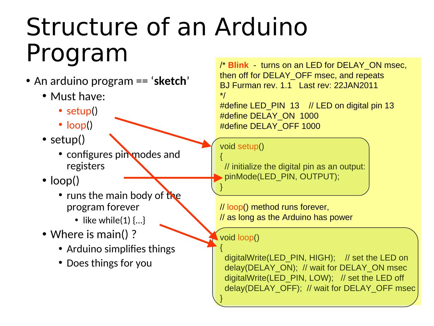
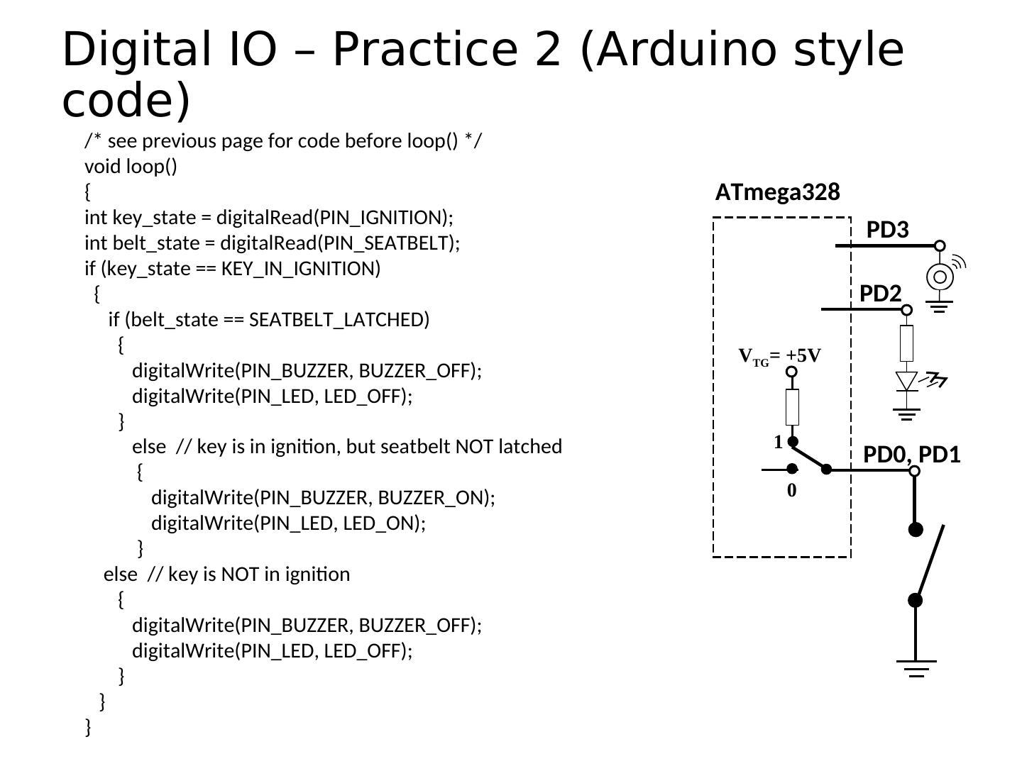
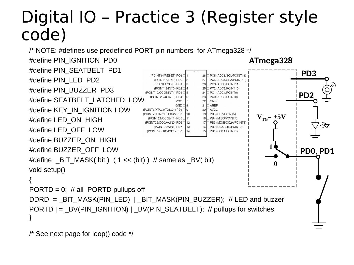
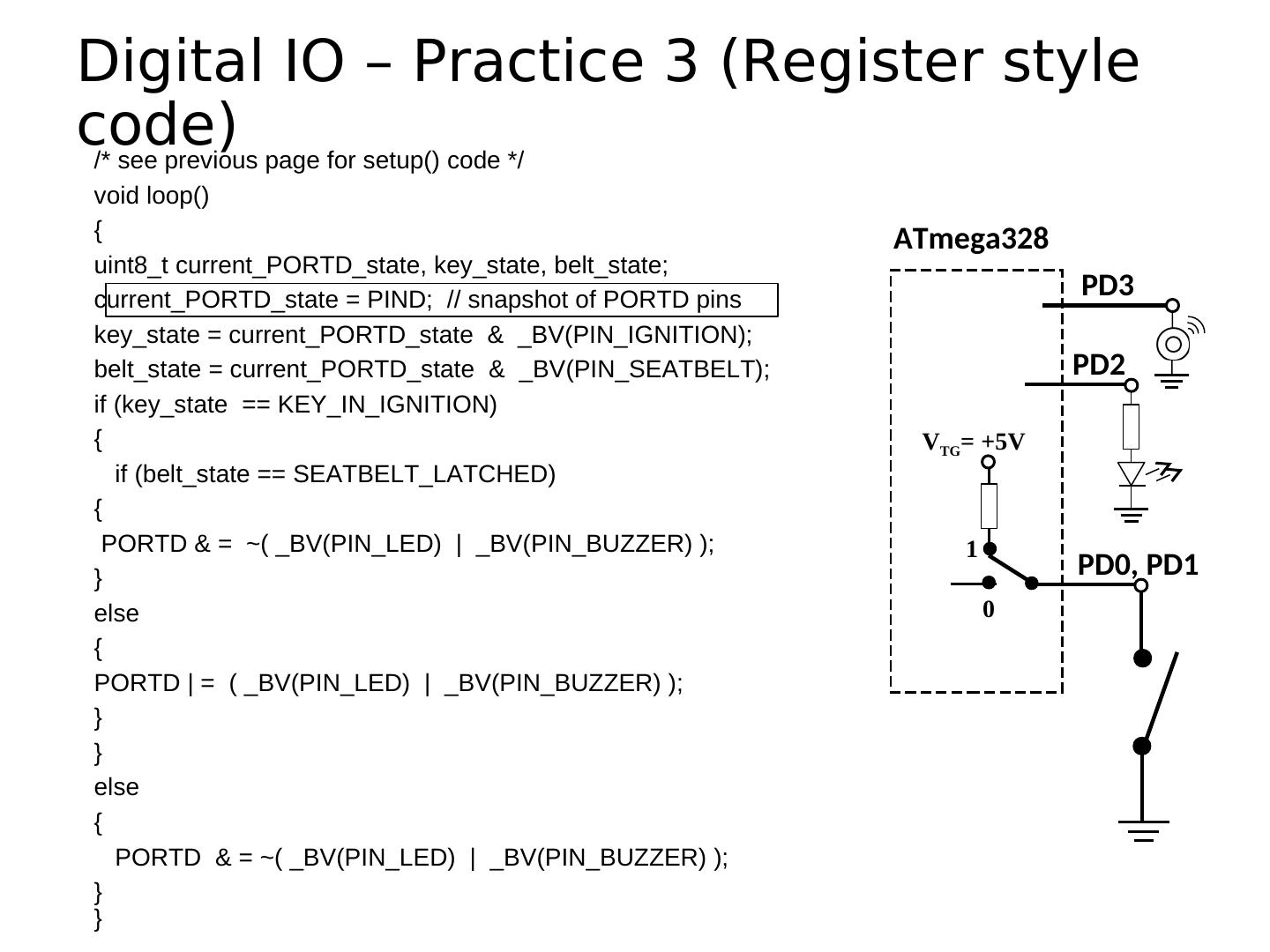
17 . Setting the Pin Data Direction • Arduino • pinMode(pin_no., dir) • Ex. Make Arduino pin 3 (PD3) an output • pinMode(3, OUTPUT); • pinMode(PIN_D3, OUTPUT); // with me106.h • Note: one pin at a time • Suppose you wanted Arduino pins 3, 5, and 7 (PD3, PD5, and PD7) to be outputs? • Is there a way to make them all outputs at the same time? • Yes! Answer coming later…
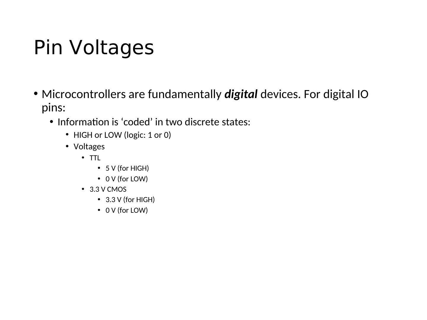
18 .Pin Voltages • Microcontrollers are fundamentally digital devices. For digital IO pins: • Information is ‘coded’ in two discrete states: • HIGH or LOW (logic: 1 or 0) • Voltages • TTL • 5 V (for HIGH) • 0 V (for LOW) • 3.3 V CMOS • 3.3 V (for HIGH) • 0 V (for LOW)
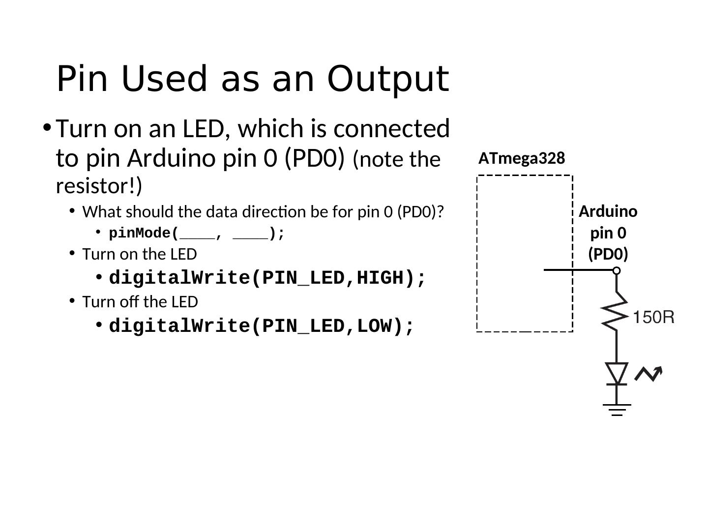
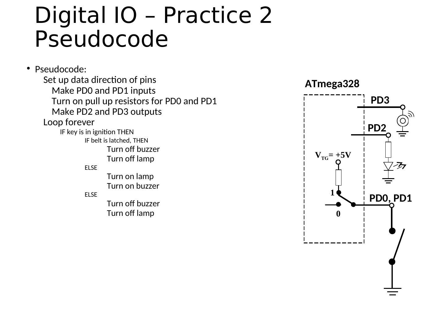
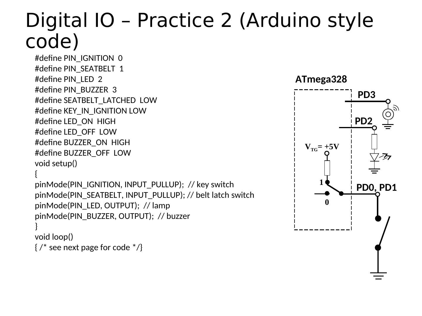
19 . Pin Used as an Output • Turn on an LED, which is connected to pin Arduino pin 0 (PD0) (note the ATmega328 resistor!) • What should the data direction be for pin 0 (PD0)? Arduino • pinMode(____, ____); pin 0 • Turn on the LED (PD0) • digitalWrite(PIN_LED,HIGH); • Turn off the LED • digitalWrite(PIN_LED,LOW);
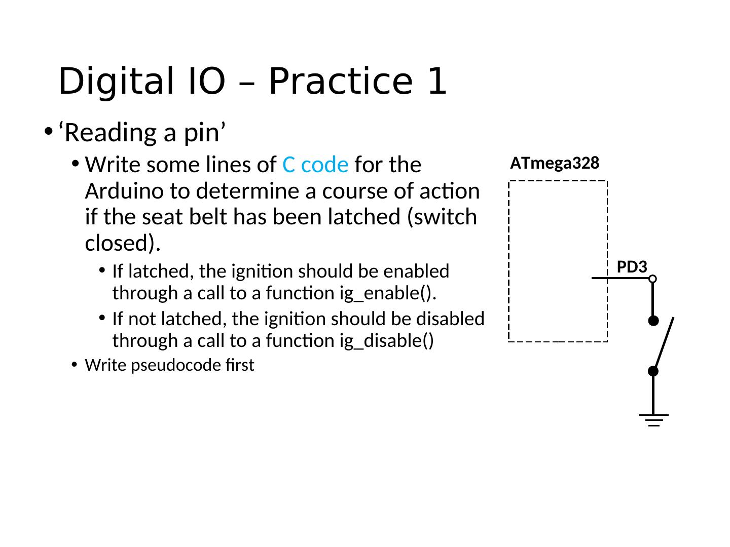
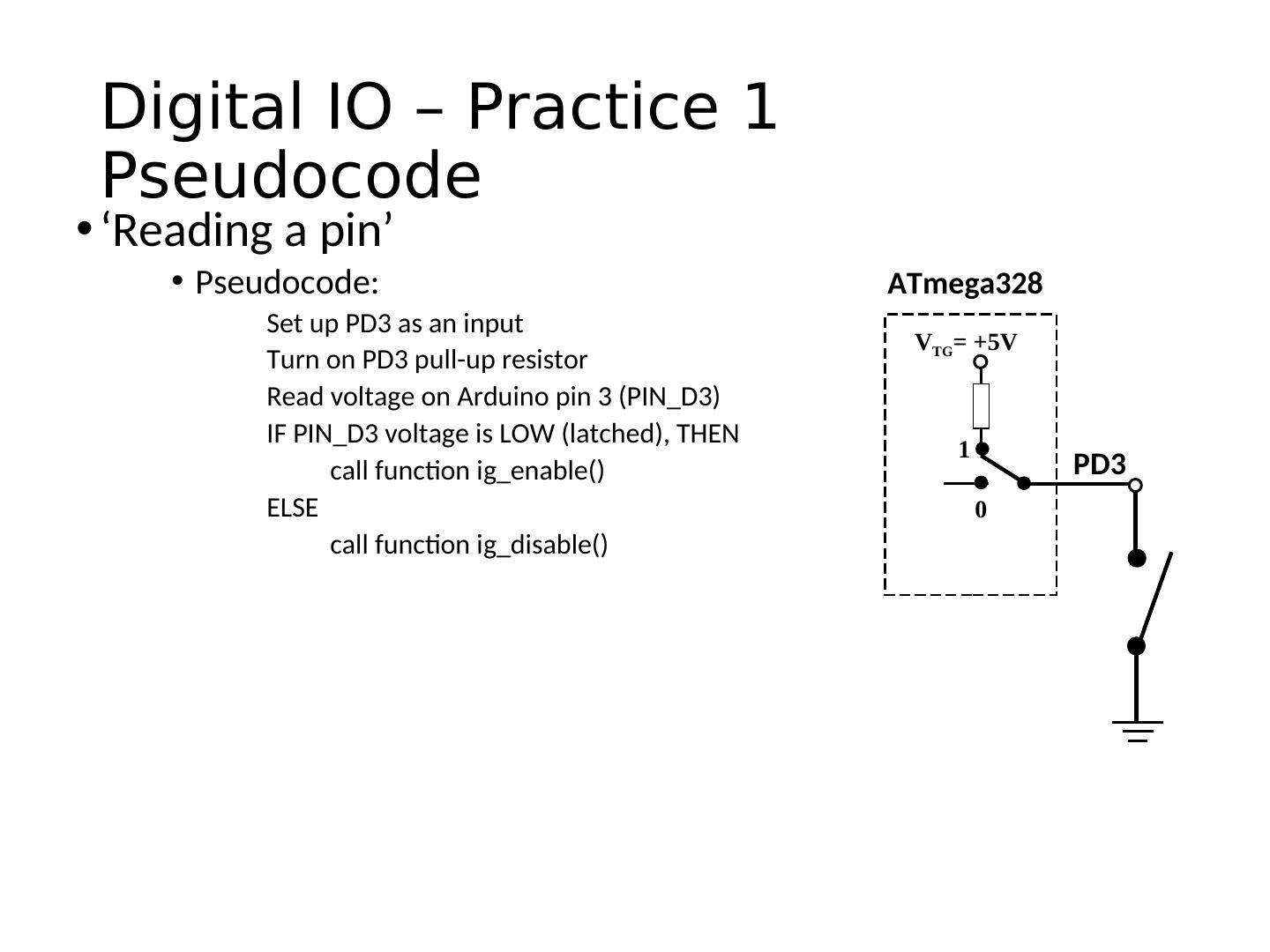
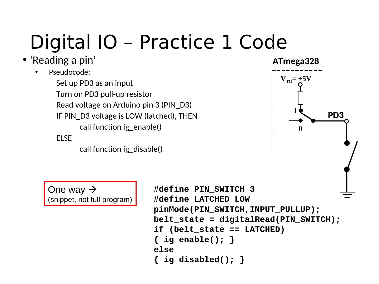
20 . Pins as Inputs and Pull-up Resistors - 1 • Using a switch as a sensor • Ex. Seat belt sensor ATmega328 • Detect the switch state • What should the data direction be for Arduino pin 3 (PD3)? • pinMode(____, ____); Arduino • What will the voltage be on PD3 when the switch is closed? pin 3 • What will the voltage be on PD3 when the switch is open? (PD3) • Indeterminate! SPST momentary
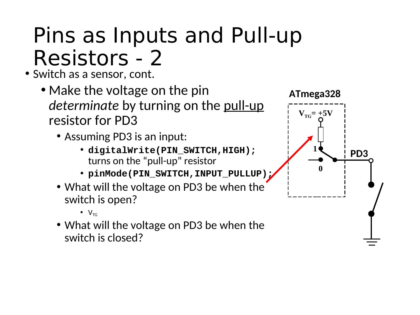
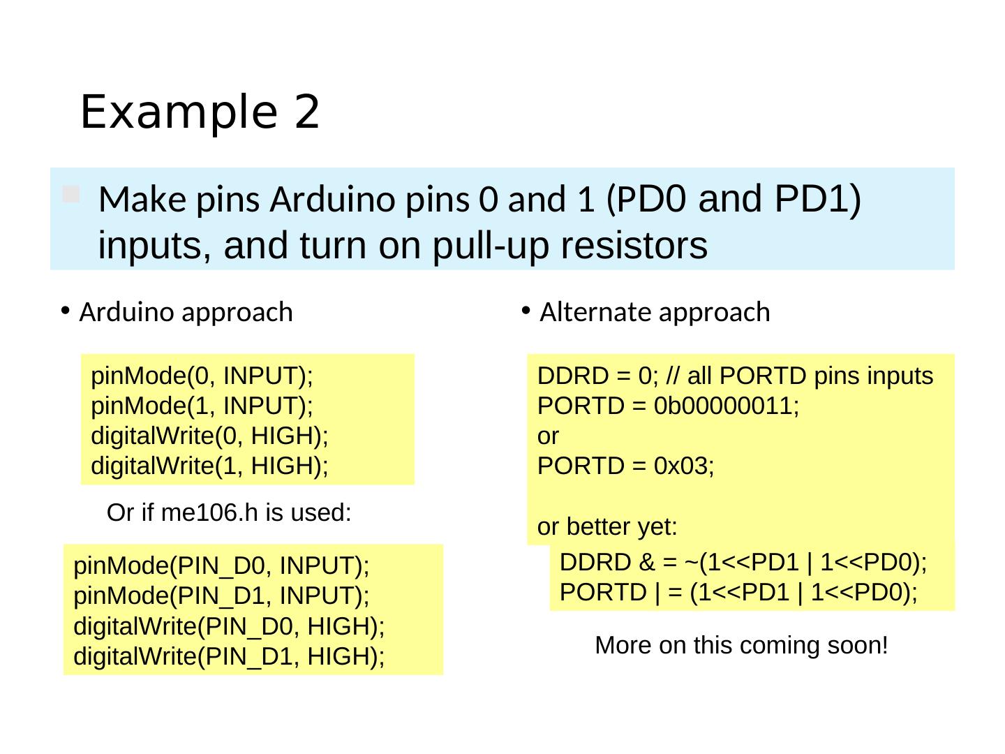
21 . Pins as Inputs and Pull-up Resistors - 2 • Switch as a sensor, cont. • Make the voltage on the pin ATmega328 determinate by turning on the pull-up VTG= +5V resistor for PD3 • Assuming PD3 is an input: • digitalWrite(PIN_SWITCH,HIGH); 1 PD3 turns on the “pull-up” resistor 0 • pinMode(PIN_SWITCH,INPUT_PULLUP); • What will the voltage on PD3 be when the switch is open? • VTG • What will the voltage on PD3 be when the switch is closed?
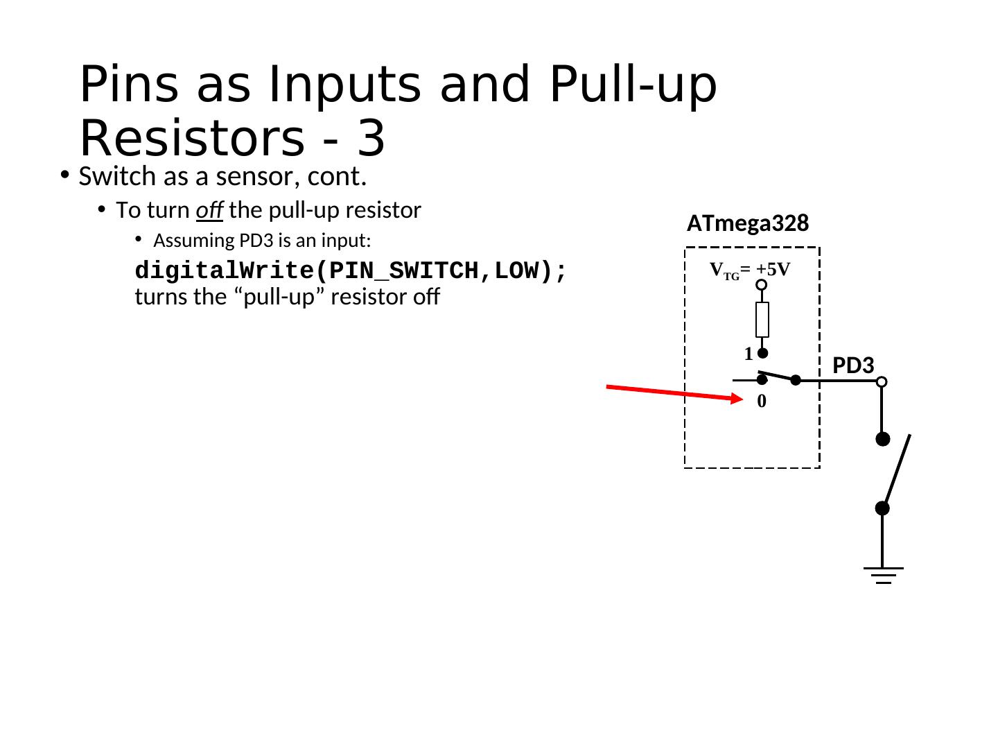
22 . Pins as Inputs and Pull-up Resistors - 3 • Switch as a sensor, cont. • To turn off the pull-up resistor ATmega328 • Assuming PD3 is an input: digitalWrite(PIN_SWITCH,LOW); VTG= +5V turns the “pull-up” resistor off 1 PD3 0
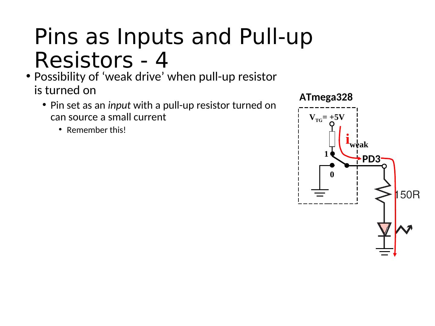
23 . Pins as Inputs and Pull-up Resistors - 4 • Possibility of ‘weak drive’ when pull-up resistor is turned on ATmega328 • Pin set as an input with a pull-up resistor turned on can source a small current VTG= +5V • Remember this! iweak 1 PD3 0
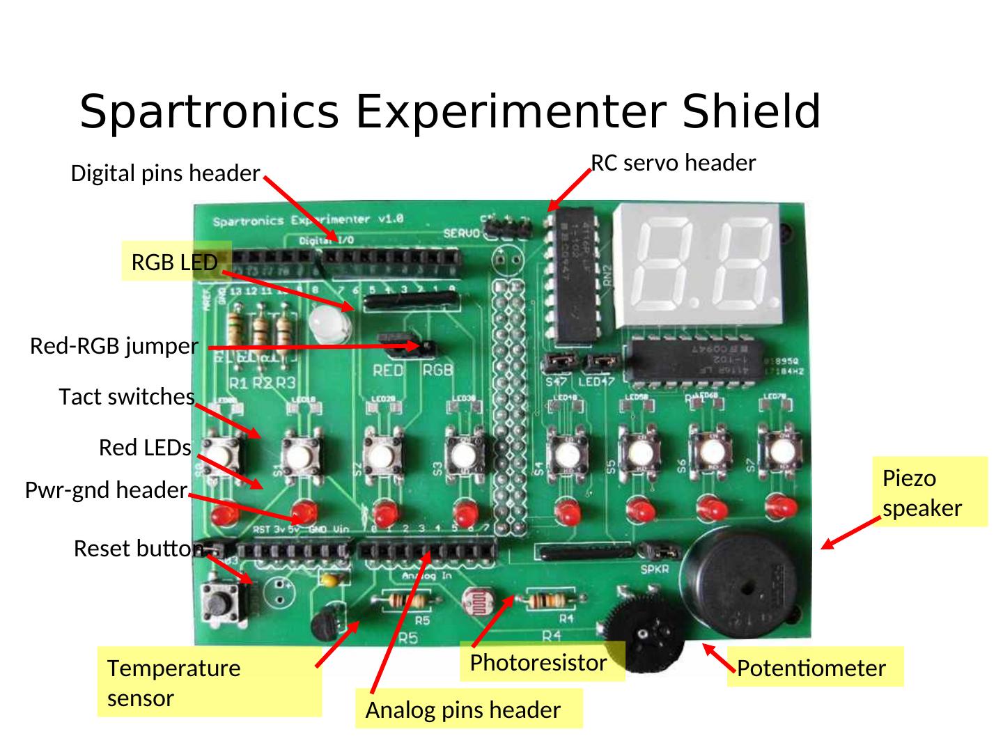
24 . Spartronics Experimenter Shield Digital pins header RC servo header RGB LED Red-RGB jumper Tact switches Red LEDs Pwr-gnd header Piezo speaker Reset button Temperature Photoresistor Potentiometer sensor Analog pins header
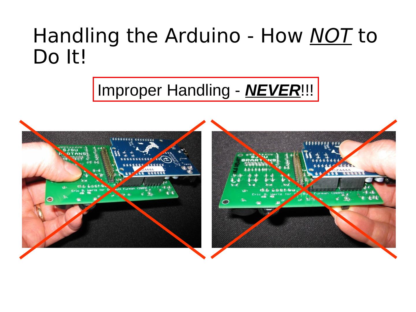
25 .Handling the Arduino - How NOT to Do It! Improper Handling - NEVER!!!
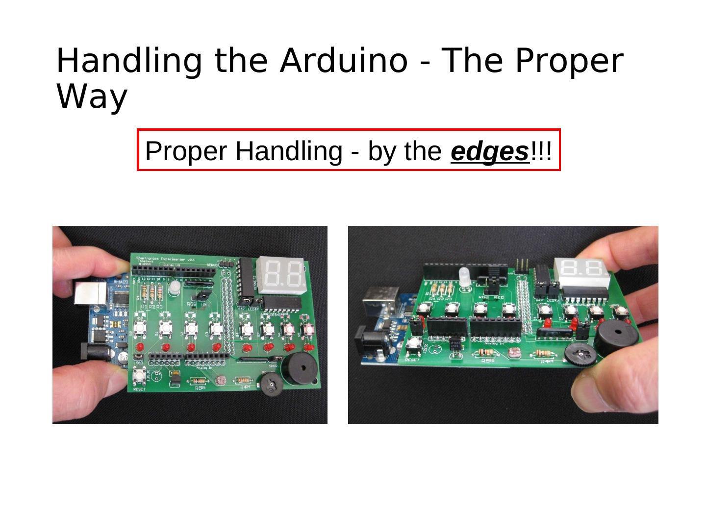
26 .Handling the Arduino - The Proper Way Proper Handling - by the edges!!!
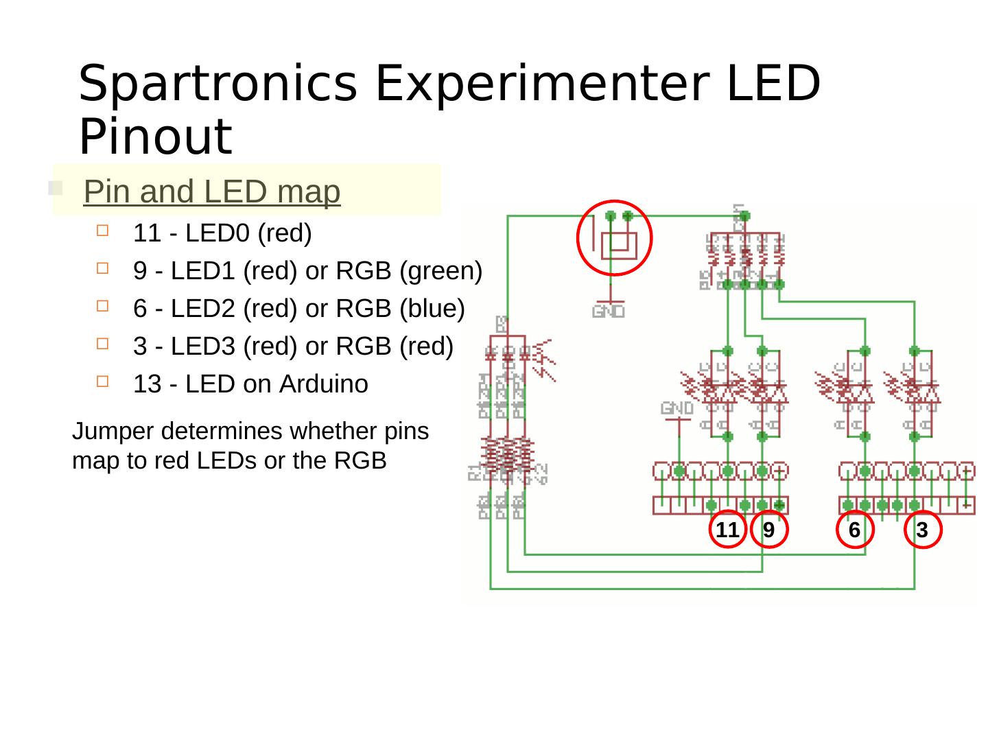
27 . Spartronics Experimenter LED Pinout Pin and LED map 11 - LED0 (red) 9 - LED1 (red) or RGB (green) 6 - LED2 (red) or RGB (blue) 3 - LED3 (red) or RGB (red) 13 - LED on Arduino Jumper determines whether pins map to red LEDs or the RGB 11 9 6 3
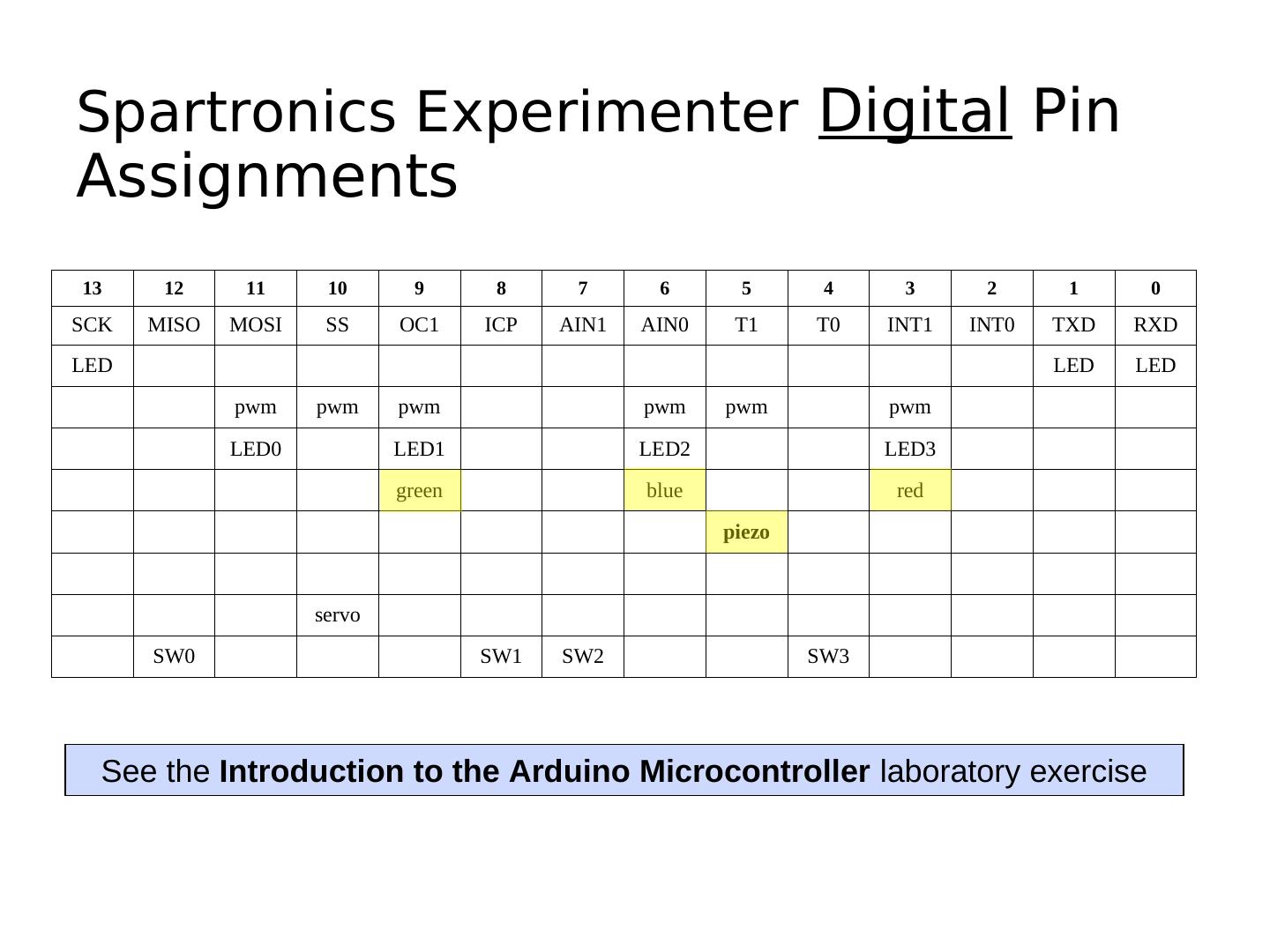
28 .Spartronics Experimenter Digital Pin Assignments 13 12 11 10 9 8 7 6 5 4 3 2 1 0 SCK MISO MOSI SS OC1 ICP AIN1 AIN0 T1 T0 INT1 INT0 TXD RXD LED LED LED pwm pwm pwm pwm pwm pwm LED0 LED1 LED2 LED3 green blue red piezo servo SW0 SW1 SW2 SW3 See the Introduction to the Arduino Microcontroller laboratory exercise
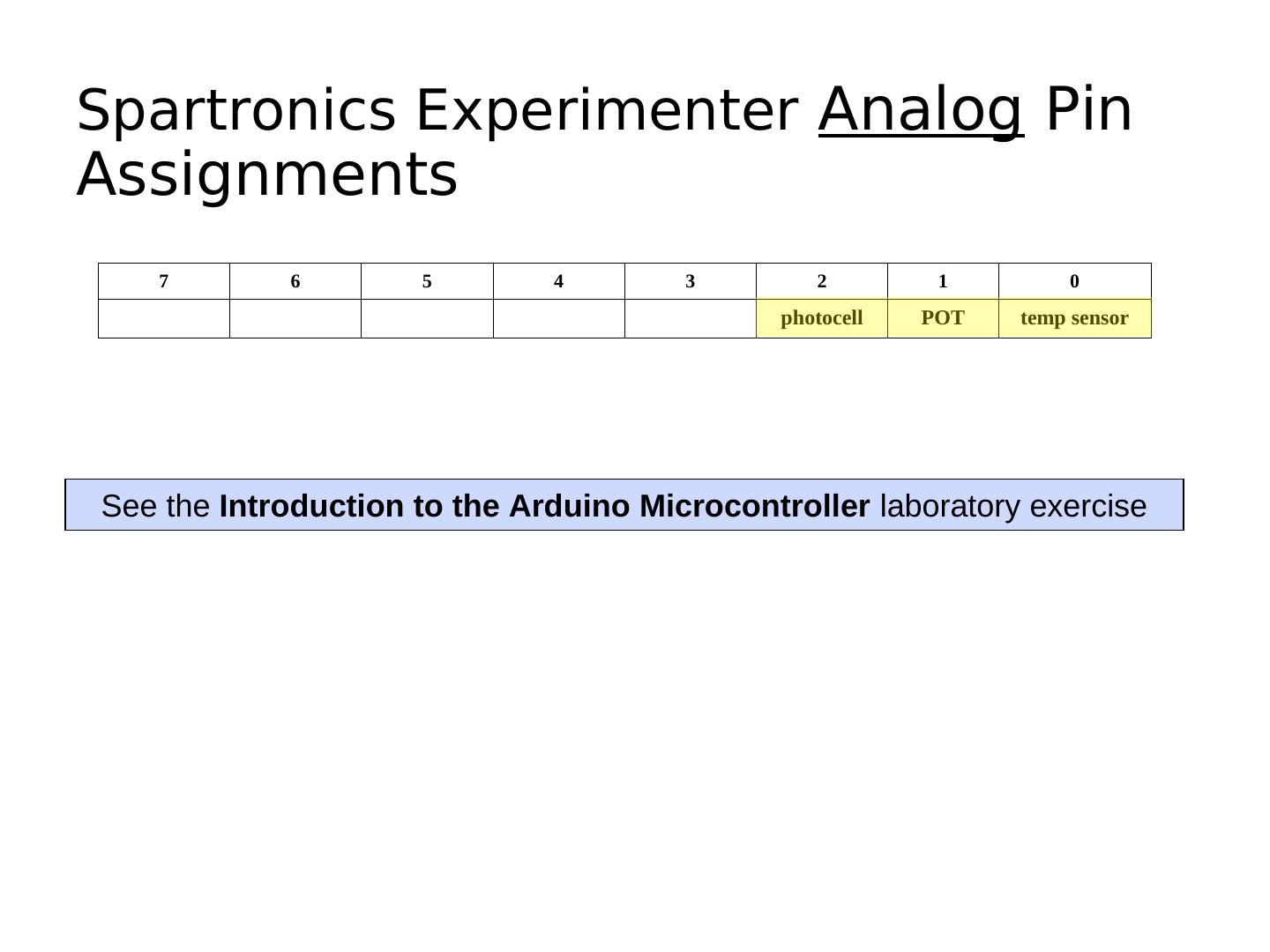
29 .Spartronics Experimenter Analog Pin Assignments 7 6 5 4 3 2 1 0 photocell POT temp sensor See the Introduction to the Arduino Microcontroller laboratory exercise
3秒后跳转登录页面
去登陆

