- 快召唤伙伴们来围观吧
- 微博 QQ QQ空间 贴吧
- 文档嵌入链接
- 复制
- 微信扫一扫分享
- 已成功复制到剪贴板
PULLEY BLOCK AND TACKLE Compound Drive Pulley Trains
展开查看详情
1 .PULLEY BLOCK AND TACKLE Compound Drive Pulley Trains
2 .Pulleys
3 .Building Drive Robot Trains
4 . Building Robot Drive Trains 1. Building Robot Drive Trains is the first volume in the new "Robot DNA" series by McGraw-Hill/TAB Electronics. 2. It is just what robotics hobbyists need to build an effective drive train using inexpensive, inexpensive off-the-shelf parts. 3. No heavy-duty “tech speak” 4. Focuses on the actual concepts and applications necessary to build – and understand -- the critical force-conveying systems. 5. If you want a clear, straightforward guide to the nuts-and- bolts of drive trains, this is the way to go.
5 . Building Robot Drive Trains • Chapters include: • The Basics of Robot Locomotion * • Motor Types: An Overview * • Using DC Motors * • Using RC Servo Motors * • Using Stepper Motors * • Motor Mounting * • Basic Motor Control * • Advanced Motor Control * • Electronics Interfacing * • Wheels and Treads * • Locomotion for Multipods * • Glossary of Terms, Tables, Formulas * 75 illustrations
6 .Pulleys • Pulley are wheels and axles with a groove around the outside • A pulley needs a rope, chain or belt around the groove to make it do work
7 . Pulley Examples • Pulley reverses the direction of force • Two or more pulleys connected together permit a heavy load to be lifted with less force http://www.sciencemuseum.org.uk/on-line/leonardo/InventorsToolbox.asp
8 . Lifting Pulleys • Lifting Pulleys in transmission systems are: 1. Single pulley 2. Moveable pulley 3. Block and Tackle
9 .Single Pulleys
10 .Fixed (single) pulley Fixed Pulley: •Wheel attached to surface •Changes the direction of the applied force •NO mechanical advantage – same amount of force is required
11 .Why no MA in a Single Pulley? • The resistance arm and the effort arm are both the radius of the pulley. • Since they are equal, there is no mechanical advantage.
12 . Single Pulley • Provides change of motion, but no mechanical advantage 100 ft 100 lbs 100 lbs 100 lbs 100 lbs
13 .Movable pulley
14 .Movable pulley Movable Pulley: • Pulley moves along the rope • Wheel supports the load • Effort is in the same direction as movement • Reduces the forces needed to move an object
15 .MA in a Moveable pulley • A moveable pulley is a second-class pulley. • The effort arm is the diameter and the resistance arm is the radius. • MA = dE ÷ dR • MA = 2 ÷ 1 = 2 Mechanical Advantage = 2
16 .Another Moveable pulley • Provides change of direction and a mechanical advantage of 1:2 (at the expense of having to increase the amount of line to pull) 50 lbs 50 lbs These kinds of 50 lbs diagrams are easier 50 lbs 100 lbs100 lbs to analyze
17 . In the second picture, the weight is held by two ropes instead of one. That means the weight is split equally between the two ropes, so each one holds only half the weight. http://www.swe.org/iac/LP/pulley_03.html
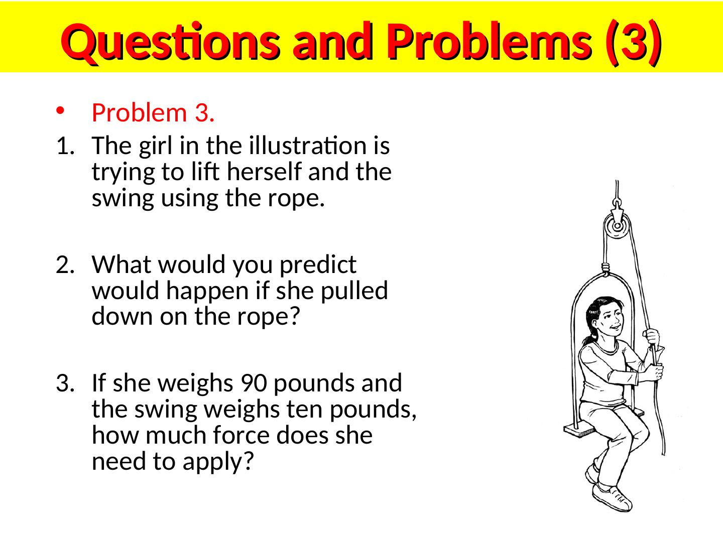
18 .COMBINED PULLEY Combined (double) Pulley: •Has at least two wheels •The more complex the pulley, the more the effort needed to move the object decreases
19 .COMBINED PULLEY • The effort needed to lift the load is less than half the weight of the load. • The main disadvantage is it travels a very long distance.
20 . Mechanical Advantage • Mechanical Advantage is the same as the number of ropes supporting the object MA=2 MA=2 MA=4
21 . How about these? Calculate MA for these and similar
22 . Pulley Calculations
23 . Pulleys as used in robots • A pulley is basically a wheel with a groove in the circumference of the wheel, with a belt or cable being fed around the groove. • Pulleys create a mechanical advantage by connecting a small input drive pulley to a larger follower with a belt. Driver Follower (Effort) (Resistance)
24 .Mechanical Advantage of a Pulley Drive Train MA = FOLLOWER ÷ DRIVER Driver Follower 1mm 4mm • The Pulley Drive Train above produces an MA of 4. This means 10 lbs of input torque will create 40 lbs output, but the driver must rotate 4 times to rotate output 1 time. Speed is reduced by 4.
25 . Mechanical Advantage MA = FOLLOWER ÷ DRIVER Driver Follower 3mm 9mm Driver Follower 2mm 14mm
26 . Increasing Speed • Increase the speed of the output by using a larger driver gear and a smaller follower gear. Speed increases and power decreases. Driver Follower 4mm 1mm
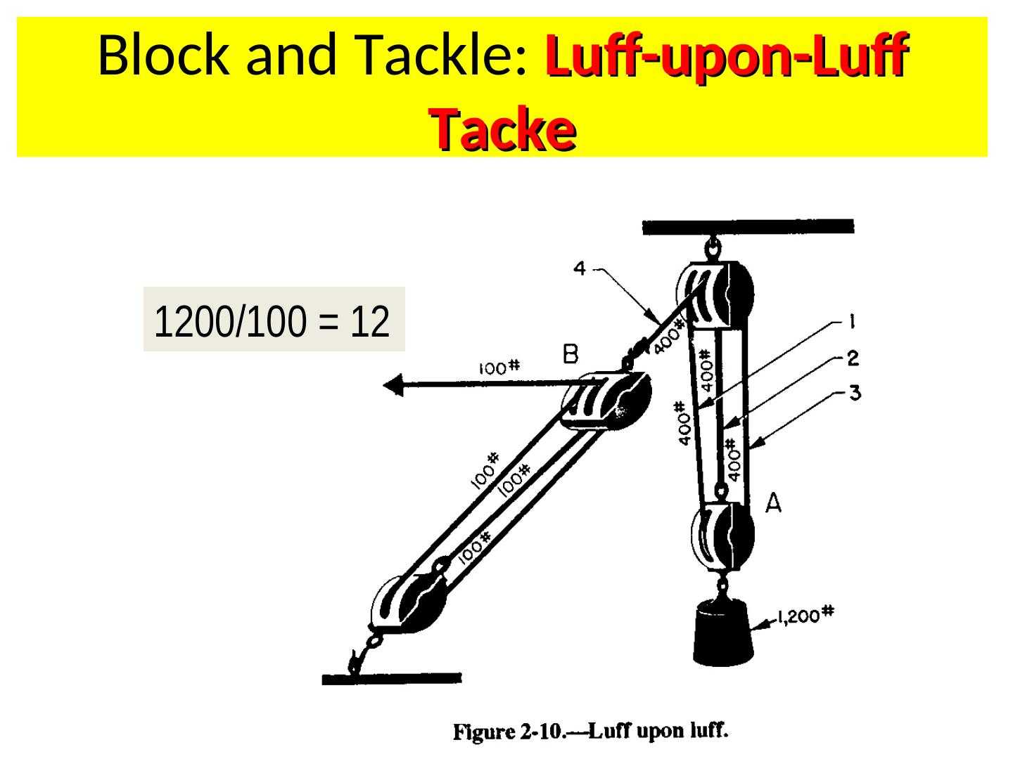
27 . Compound Drive Pulley Trains • A Compound Drive Pulley Train has pairs of pulleys working in combination, • with the follower of one pulley sharing the same axle as the driver of the next sequential pulley train.
28 .Example 1: Compound Drive Pulley Trains MA = (FOLLOWER 1 * FOLLOWER 2) ÷ (DRIVER 1 & DRIVER 2) – Driver 1 = 2mm Follower 1 = 8mm – Driver 2 = 3mm Follower 2 = 9mm Calculate MA / (8*9) (2*3) = 72/6 = 12)
29 .Example 2: Compound Drive Pulley Trains MA = (FOLLOWER 1 X FOLLOWER 2) ÷ (DRIVER 1 x DRIVER 2) – Driver 1 = 3mm Follower 1 = 9mm – Driver 2 = 2mm Follower 2 = 14mm Calculate MA


