- 快召唤伙伴们来围观吧
- 微博 QQ QQ空间 贴吧
- 文档嵌入链接
- <iframe src="https://www.slidestalk.com/u70/Intel_SGX_Explained?embed" frame border="0" width="640" height="360" scrolling="no" allowfullscreen="true">复制
- 微信扫一扫分享
Intel SGX 技术剖析
展开查看详情
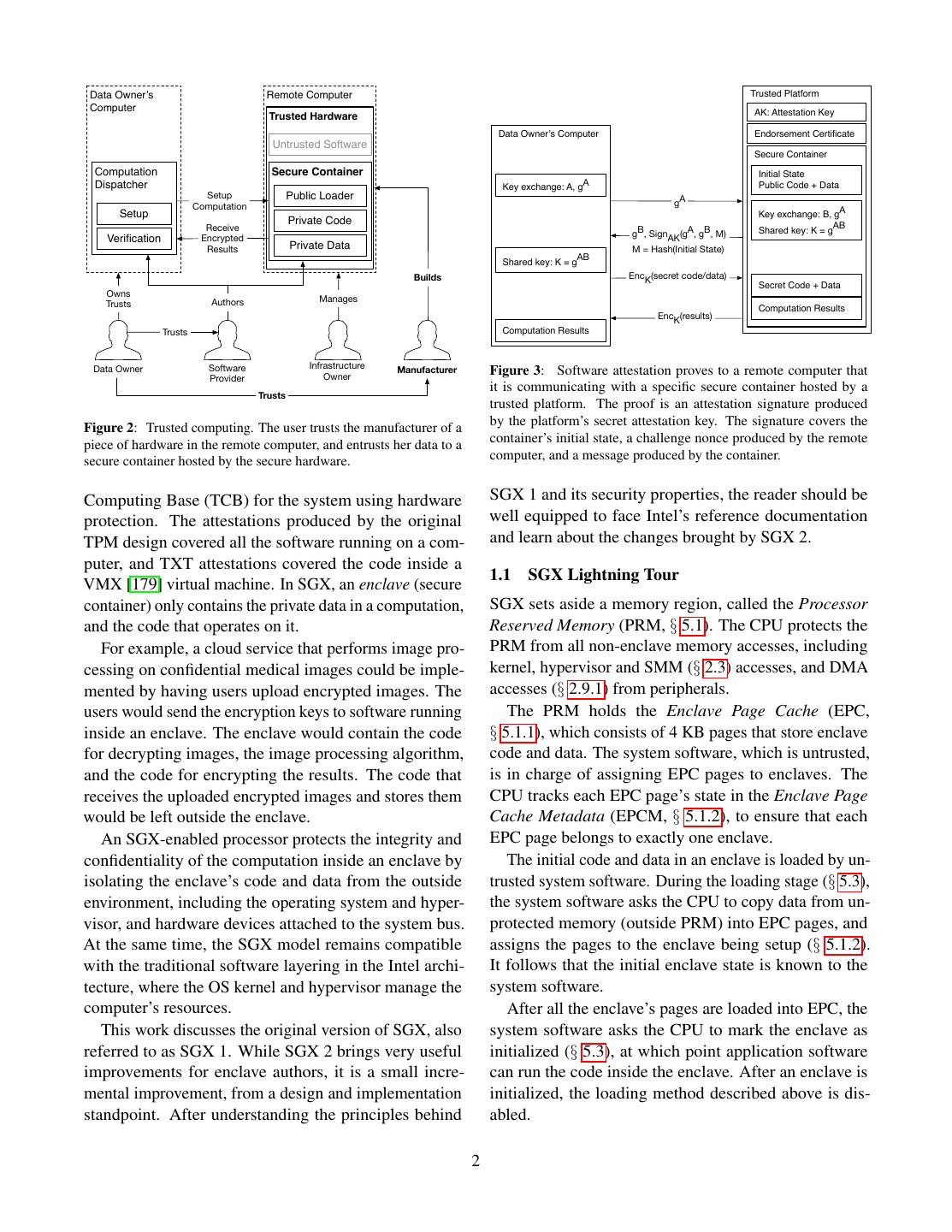
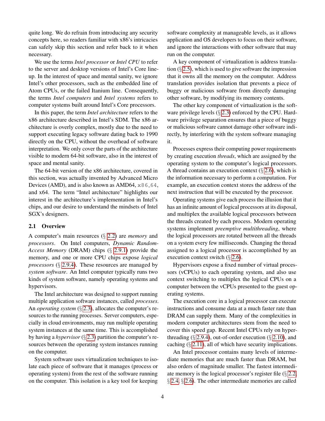
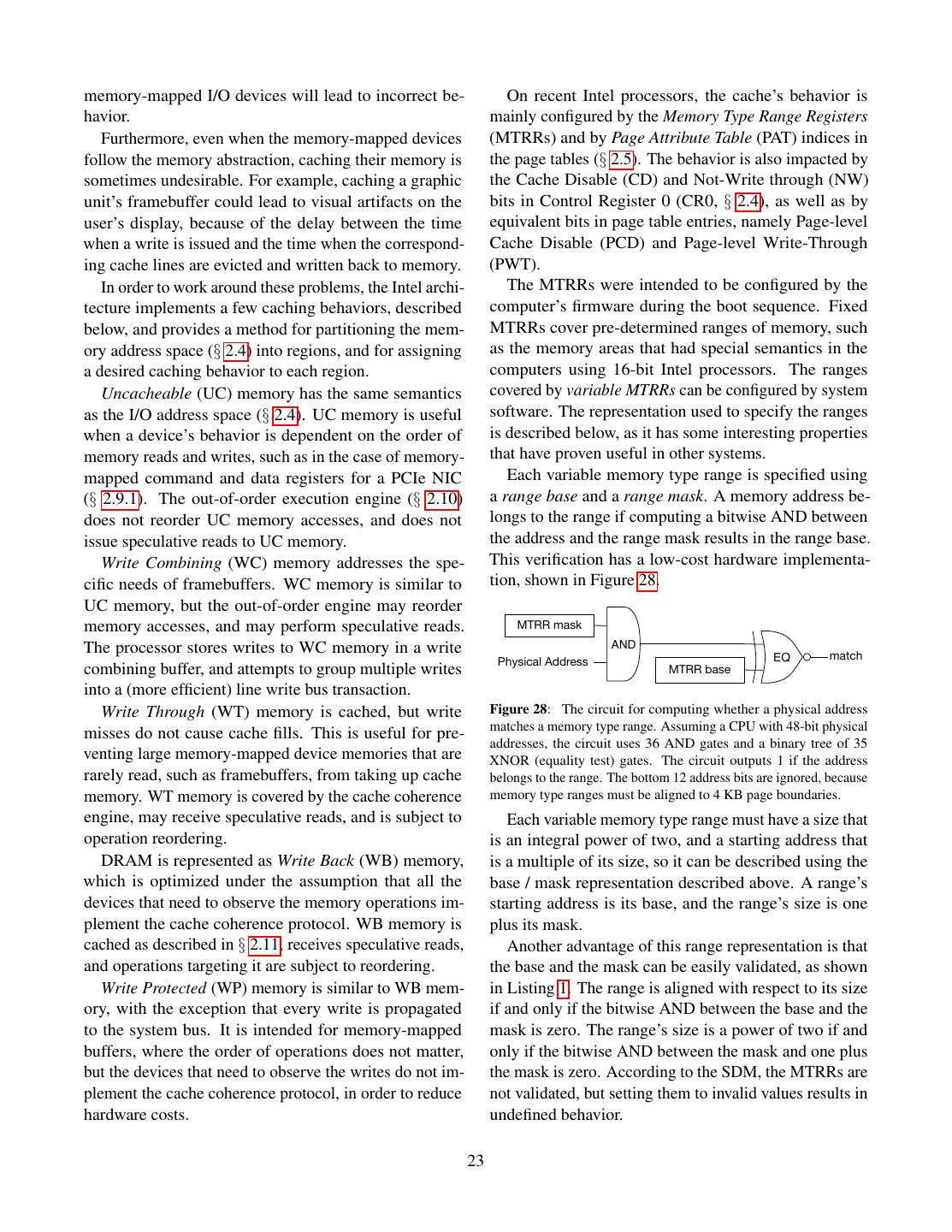
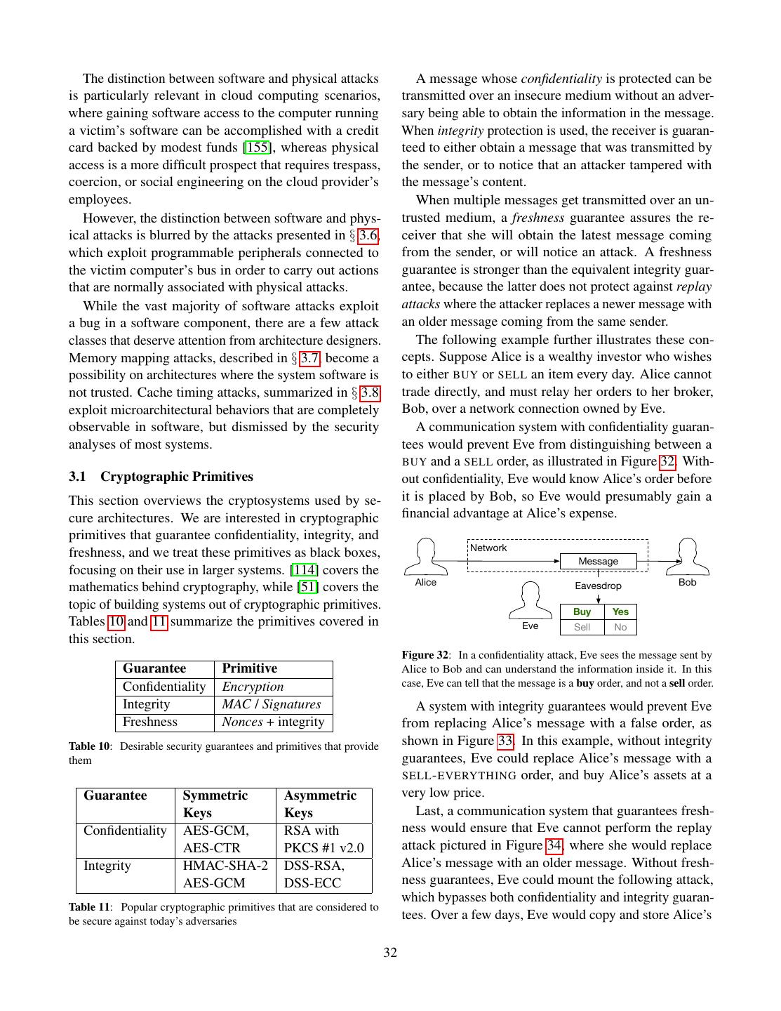
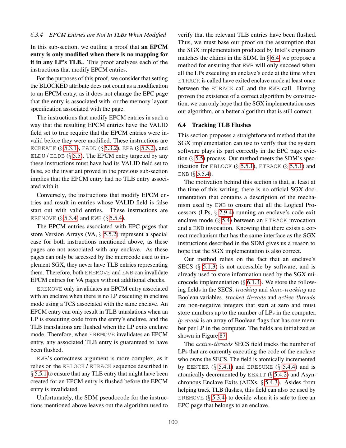
1 . Intel SGX Explained Victor Costan and Srinivas Devadas victor@costan.us, devadas@mit.edu Computer Science and Artificial Intelligence Laboratory Massachusetts Institute of Technology A BSTRACT Data Owner’s Remote Computer Computer Intel’s Software Guard Extensions (SGX) is a set of Untrusted Software extensions to the Intel architecture that aims to pro- Computation Container vide integrity and confidentiality guarantees to security- Dispatcher sensitive computation performed on a computer where Setup Computation all the privileged software (kernel, hypervisor, etc) is Setup Private Code Receive potentially malicious. Verification Encrypted Results Private Data This paper analyzes Intel SGX, based on the 3 pa- pers [14, 78, 137] that introduced it, on the Intel Software Developer’s Manual [100] (which supersedes the SGX Owns Authors Manages manuals [94, 98]), on an ISCA 2015 tutorial [102], and Trusts on two patents [108, 136]. We use the papers, reference Trusts manuals, and tutorial as primary data sources, and only draw on the patents to fill in missing information. Data Owner Software Infrastructure Provider Owner This paper’s contributions are a summary of the Intel-specific architectural and micro-architectural details Figure 1: Secure remote computation. A user relies on a remote needed to understand SGX, a detailed and structured pre- computer, owned by an untrusted party, to perform some computation sentation of the publicly available information on SGX, on her data. The user has some assurance of the computation’s a series of intelligent guesses about some important but integrity and confidentiality. undocumented aspects of SGX, and an analysis of SGX’s security properties. performed on it. SGX relies on software attestation, like its predeces- 1 OVERVIEW sors, the TPM [71] and TXT [70]. Attestation (Figure 3) Secure remote computation (Figure 1) is the problem proves to a user that she is communicating with a specific of executing software on a remote computer owned and piece of software running in a secure container hosted maintained by an untrusted party, with some integrity by the trusted hardware. The proof is a cryptographic and confidentiality guarantees. In the general setting, signature that certifies the hash of the secure container’s secure remote computation is an unsolved problem. Fully contents. It follows that the remote computer’s owner can Homomorphic Encryption [61] solves the problem for a load any software in a secure container, but the remote limited family of computations, but has an impractical computation service user will refuse to load her data into performance overhead [138]. a secure container whose contents’ hash does not match Intel’s Software Guard Extensions (SGX) is the latest the expected value. iteration in a long line of trusted computing (Figure 2) The remote computation service user verifies the at- designs, which aim to solve the secure remote compu- testation key used to produce the signature against an tation problem by leveraging trusted hardware in the endorsement certificate created by the trusted hardware’s remote computer. The trusted hardware establishes a se- manufacturer. The certificate states that the attestation cure container, and the remote computation service user key is only known to the trusted hardware, and only used uploads the desired computation and data into the secure for the purpose of attestation. container. The trusted hardware protects the data’s con- SGX stands out from its predecessors by the amount fidentiality and integrity while the computation is being of code covered by the attestation, which is in the Trusted 1
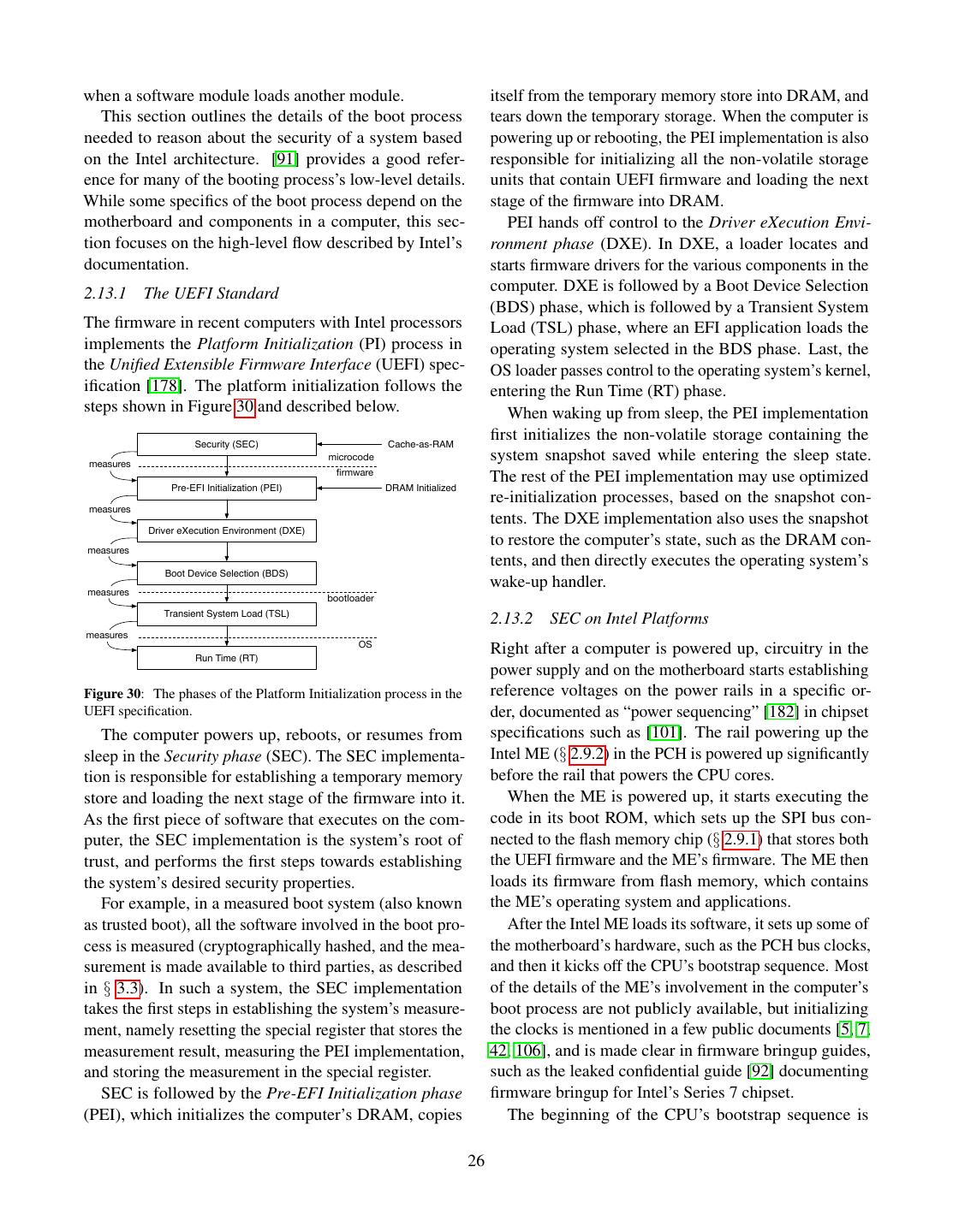
2 . Data Owner’s Remote Computer Trusted Platform Computer AK: Attestation Key Trusted Hardware Data Owner’s Computer Endorsement Certificate Untrusted Software Secure Container Computation Secure Container Initial State Dispatcher Key exchange: A, gA Public Code + Data Setup Public Loader Computation gA A Setup Key exchange: B, g Private Code Receive B A B g , SignAK(g , g , M) Shared key: K = gAB Verification Encrypted Results Private Data M = Hash(Initial State) Shared key: K = gAB Builds EncK(secret code/data) Secret Code + Data Owns Authors Manages Trusts Computation Results EncK(results) Trusts Computation Results Data Owner Software Infrastructure Manufacturer Owner Figure 3: Software attestation proves to a remote computer that Provider it is communicating with a specific secure container hosted by a Trusts trusted platform. The proof is an attestation signature produced Figure 2: Trusted computing. The user trusts the manufacturer of a by the platform’s secret attestation key. The signature covers the piece of hardware in the remote computer, and entrusts her data to a container’s initial state, a challenge nonce produced by the remote secure container hosted by the secure hardware. computer, and a message produced by the container. Computing Base (TCB) for the system using hardware SGX 1 and its security properties, the reader should be protection. The attestations produced by the original well equipped to face Intel’s reference documentation TPM design covered all the software running on a com- and learn about the changes brought by SGX 2. puter, and TXT attestations covered the code inside a 1.1 SGX Lightning Tour VMX [179] virtual machine. In SGX, an enclave (secure container) only contains the private data in a computation, SGX sets aside a memory region, called the Processor and the code that operates on it. Reserved Memory (PRM, § 5.1). The CPU protects the For example, a cloud service that performs image pro- PRM from all non-enclave memory accesses, including cessing on confidential medical images could be imple- kernel, hypervisor and SMM (§ 2.3) accesses, and DMA mented by having users upload encrypted images. The accesses (§ 2.9.1) from peripherals. users would send the encryption keys to software running The PRM holds the Enclave Page Cache (EPC, inside an enclave. The enclave would contain the code § 5.1.1), which consists of 4 KB pages that store enclave for decrypting images, the image processing algorithm, code and data. The system software, which is untrusted, and the code for encrypting the results. The code that is in charge of assigning EPC pages to enclaves. The receives the uploaded encrypted images and stores them CPU tracks each EPC page’s state in the Enclave Page would be left outside the enclave. Cache Metadata (EPCM, § 5.1.2), to ensure that each An SGX-enabled processor protects the integrity and EPC page belongs to exactly one enclave. confidentiality of the computation inside an enclave by The initial code and data in an enclave is loaded by un- isolating the enclave’s code and data from the outside trusted system software. During the loading stage (§ 5.3), environment, including the operating system and hyper- the system software asks the CPU to copy data from un- visor, and hardware devices attached to the system bus. protected memory (outside PRM) into EPC pages, and At the same time, the SGX model remains compatible assigns the pages to the enclave being setup (§ 5.1.2). with the traditional software layering in the Intel archi- It follows that the initial enclave state is known to the tecture, where the OS kernel and hypervisor manage the system software. computer’s resources. After all the enclave’s pages are loaded into EPC, the This work discusses the original version of SGX, also system software asks the CPU to mark the enclave as referred to as SGX 1. While SGX 2 brings very useful initialized (§ 5.3), at which point application software improvements for enclave authors, it is a small incre- can run the code inside the enclave. After an enclave is mental improvement, from a design and implementation initialized, the loading method described above is dis- standpoint. After understanding the principles behind abled. 2
3 . While an enclave is loaded, its contents is cryptograph- description of SGX’s programming model, mostly based ically hashed by the CPU. When the enclave is initialized, on Intel’s Software Development Manual. the hash is finalized, and becomes the enclave’s measure- Section 6 analyzes other public sources of informa- ment hash (§ 5.6). tion, such as Intel’s SGX-related patents, to fill in some A remote party can undergo a software attestation of the missing details in the SGX description. The sec- process (§ 5.8) to convince itself that it is communicating tion culminates in a detailed review of SGX’s security with an enclave that has a specific measurement hash, properties that draws on information presented in the and is running in a secure environment. rest of the paper. This review outlines some troubling Execution flow can only enter an enclave via special gaps in SGX’s security guarantees, as well as some areas CPU instructions (§ 5.4), which are similar to the mech- where no conclusions can be drawn without additional anism for switching from user mode to kernel mode. information from Intel. Enclave execution always happens in protected mode, at That being said, perhaps the most troubling finding in ring 3, and uses the address translation set up by the OS our security analysis is that Intel added a launch control kernel and hypervisor. feature to SGX that forces each computer’s owner to gain To avoid leaking private data, a CPU that is executing approval from a third party (which is currently Intel) for enclave code does not directly service an interrupt, fault any enclave that the owner wishes to use on the com- (e.g., a page fault) or VM exit. Instead, the CPU first per- puter. § 5.9 explains that the only publicly documented forms an Asynchronous Enclave Exit (§ 5.4.3) to switch intended use for this launch control feature is a licensing from enclave code to ring 3 code, and then services the mechanism that requires software developers to enter a interrupt, fault, or VM exit. The CPU performs an AEX (yet unspecified) business agreement with Intel to be able by saving the CPU state into a predefined area inside the to author software that takes advantage of SGX’s protec- enclave and transfers control to a pre-specified instruc- tions. All the official documentation carefully sidesteps tion outside the enclave, replacing CPU registers with this issue, and has a minimal amount of hints that lead to synthetic values. the Intel’s patents on SGX. Only these patents disclose The allocation of EPC pages to enclaves is delegated the existence of licensing plans. to the OS kernel (or hypervisor). The OS communicates The licensing issue might not bear much relevance its allocation decisions to the SGX implementation via right now, because our security analysis reveals that the special ring 0 CPU instructions (§ 5.3). The OS can also limitations in SGX’s guarantees mean that a security- evict EPC pages into untrusted DRAM and later load conscious software developer cannot in good conscience them back, using dedicated CPU instructions. SGX uses rely on SGX for secure remote computation. At the same cryptographic protections to assure the confidentiality, time, should SGX ever develop better security properties, integrity and freshness of the evicted EPC pages while the licensing scheme described above becomes a major they are stored in untrusted memory. problem, given Intel’s near-monopoly market share of desktop and server CPUs. Specifically, the licensing limi- 1.2 Outline and Troubling Findings tations effectively give Intel the power to choose winners Reasoning about the security properties of Intel’s SGX and losers in industries that rely on cloud computing. requires a significant amount of background information that is currently scattered across many sources. For this 2 C OMPUTER A RCHITECTURE BACK - reason, a significant portion of this work is dedicated to GROUND summarizing this prerequisite knowledge. This section attempts to summarize the general archi- Section 2 summarizes the relevant subset of the Intel tectural principles behind Intel’s most popular computer architecture and the micro-architectural properties of processors, as well as the peculiarities needed to reason recent Intel processors. Section 3 outlines the security about the security properties of a system running on these landscape around trusted hardware system, including processors. Unless specified otherwise, the information cryptographic tools and relevant attack classes. Last, here is summarized from Intel’s Software Development section 4 briefly describes the trusted hardware systems Manual (SDM) [100]. that make up the context in which SGX was created. Analyzing the security of a software system requires After having reviewed the background information, understanding the interactions between all the parts of section 5 provides a (sometimes painstakingly) detailed the software’s execution environment, so this section is 3
4 .quite long. We do refrain from introducing any security software complexity at manageable levels, as it allows concepts here, so readers familiar with x86’s intricacies application and OS developers to focus on their software, can safely skip this section and refer back to it when and ignore the interactions with other software that may necessary. run on the computer. We use the terms Intel processor or Intel CPU to refer A key component of virtualization is address transla- to the server and desktop versions of Intel’s Core line- tion (§ 2.5), which is used to give software the impression up. In the interest of space and mental sanity, we ignore that it owns all the memory on the computer. Address Intel’s other processors, such as the embedded line of translation provides isolation that prevents a piece of Atom CPUs, or the failed Itanium line. Consequently, buggy or malicious software from directly damaging the terms Intel computers and Intel systems refers to other software, by modifying its memory contents. computer systems built around Intel’s Core processors. The other key component of virtualization is the soft- In this paper, the term Intel architecture refers to the ware privilege levels (§ 2.3) enforced by the CPU. Hard- x86 architecture described in Intel’s SDM. The x86 ar- ware privilege separation ensures that a piece of buggy chitecture is overly complex, mostly due to the need to or malicious software cannot damage other software indi- support executing legacy software dating back to 1990 rectly, by interfering with the system software managing directly on the CPU, without the overhead of software it. interpretation. We only cover the parts of the architecture Processes express their computing power requirements visible to modern 64-bit software, also in the interest of by creating execution threads, which are assigned by the space and mental sanity. operating system to the computer’s logical processors. The 64-bit version of the x86 architecture, covered in A thread contains an execution context (§ 2.6), which is this section, was actually invented by Advanced Micro the information necessary to perform a computation. For Devices (AMD), and is also known as AMD64, x86 64, example, an execution context stores the address of the and x64. The term “Intel architecture” highlights our next instruction that will be executed by the processor. interest in the architecture’s implementation in Intel’s Operating systems give each process the illusion that it chips, and our desire to understand the mindsets of Intel has an infinite amount of logical processors at its disposal, SGX’s designers. and multiplex the available logical processors between the threads created by each process. Modern operating 2.1 Overview systems implement preemptive multithreading, where A computer’s main resources (§ 2.2) are memory and the logical processors are rotated between all the threads processors. On Intel computers, Dynamic Random- on a system every few milliseconds. Changing the thread Access Memory (DRAM) chips (§ 2.9.1) provide the assigned to a logical processor is accomplished by an memory, and one or more CPU chips expose logical execution context switch (§ 2.6). processors (§ 2.9.4). These resources are managed by Hypervisors expose a fixed number of virtual proces- system software. An Intel computer typically runs two sors (vCPUs) to each operating system, and also use kinds of system software, namely operating systems and context switching to multiplex the logical CPUs on a hypervisors. computer between the vCPUs presented to the guest op- The Intel architecture was designed to support running erating systems. multiple application software instances, called processes. The execution core in a logical processor can execute An operating system (§ 2.3), allocates the computer’s re- instructions and consume data at a much faster rate than sources to the running processes. Server computers, espe- DRAM can supply them. Many of the complexities in cially in cloud environments, may run multiple operating modern computer architectures stem from the need to system instances at the same time. This is accomplished cover this speed gap. Recent Intel CPUs rely on hyper- by having a hypervisor (§ 2.3) partition the computer’s re- threading (§ 2.9.4), out-of-order execution (§ 2.10), and sources between the operating system instances running caching (§ 2.11), all of which have security implications. on the computer. An Intel processor contains many levels of interme- System software uses virtualization techniques to iso- diate memories that are much faster than DRAM, but late each piece of software that it manages (process or also orders of magnitude smaller. The fastest intermedi- operating system) from the rest of the software running ate memory is the logical processor’s register file (§ 2.2, on the computer. This isolation is a key tool for keeping § 2.4, § 2.6). The other intermediate memories are called 4
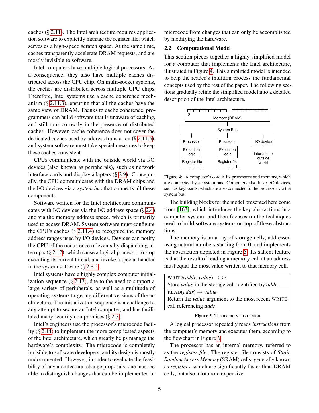
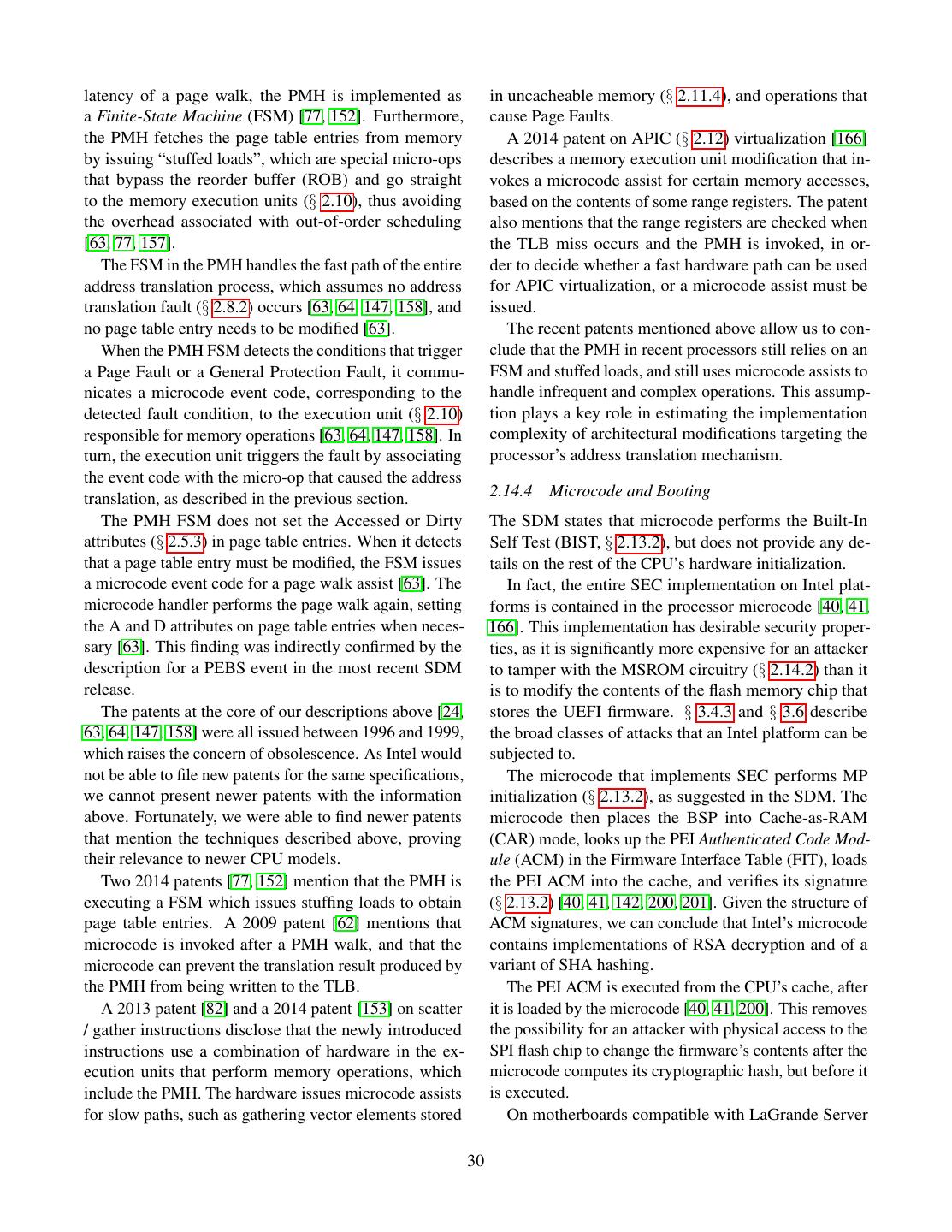
5 .caches (§ 2.11). The Intel architecture requires applica- microcode from changes that can only be accomplished tion software to explicitly manage the register file, which by modifying the hardware. serves as a high-speed scratch space. At the same time, 2.2 Computational Model caches transparently accelerate DRAM requests, and are This section pieces together a highly simplified model mostly invisible to software. for a computer that implements the Intel architecture, Intel computers have multiple logical processors. As illustrated in Figure 4. This simplified model is intended a consequence, they also have multiple caches dis- to help the reader’s intuition process the fundamental tributed across the CPU chip. On multi-socket systems, concepts used by the rest of the paper. The following sec- the caches are distributed across multiple CPU chips. tions gradually refine the simplified model into a detailed Therefore, Intel systems use a cache coherence mech- description of the Intel architecture. anism (§ 2.11.3), ensuring that all the caches have the same view of DRAM. Thanks to cache coherence, pro- … 0 grammers can build software that is unaware of caching, Memory (DRAM) and still runs correctly in the presence of distributed System Bus caches. However, cache coherence does not cover the dedicated caches used by address translation (§ 2.11.5), Processor Processor I/O device and system software must take special measures to keep Execution Execution these caches consistent. logic logic interface to outside CPUs communicate with the outside world via I/O Register file Register file world devices (also known as peripherals), such as network interface cards and display adapters (§ 2.9). Conceptu- Figure 4: A computer’s core is its processors and memory, which ally, the CPU communicates with the DRAM chips and are connected by a system bus. Computers also have I/O devices, the I/O devices via a system bus that connects all these such as keyboards, which are also connected to the processor via the components. system bus. Software written for the Intel architecture communi- The building blocks for the model presented here come cates with I/O devices via the I/O address space (§ 2.4) from [163], which introduces the key abstractions in a and via the memory address space, which is primarily computer system, and then focuses on the techniques used to access DRAM. System software must configure used to build software systems on top of these abstrac- the CPU’s caches (§ 2.11.4) to recognize the memory tions. address ranges used by I/O devices. Devices can notify The memory is an array of storage cells, addressed the CPU of the occurrence of events by dispatching in- using natural numbers starting from 0, and implements terrupts (§ 2.12), which cause a logical processor to stop the abstraction depicted in Figure 5. Its salient feature executing its current thread, and invoke a special handler is that the result of reading a memory cell at an address in the system software (§ 2.8.2). must equal the most value written to that memory cell. Intel systems have a highly complex computer initial- WRITE (addr, value) → ∅ ization sequence (§ 2.13), due to the need to support a Store value in the storage cell identified by addr. large variety of peripherals, as well as a multitude of READ (addr) → value operating systems targeting different versions of the ar- Return the value argument to the most recent WRITE chitecture. The initialization sequence is a challenge to call referencing addr. any attempt to secure an Intel computer, and has facili- tated many security compromises (§ 2.3). Figure 5: The memory abstraction Intel’s engineers use the processor’s microcode facil- A logical processor repeatedly reads instructions from ity (§ 2.14) to implement the more complicated aspects the computer’s memory and executes them, according to of the Intel architecture, which greatly helps manage the the flowchart in Figure 6. hardware’s complexity. The microcode is completely The processor has an internal memory, referred to invisible to software developers, and its design is mostly as the register file. The register file consists of Static undocumented. However, in order to evaluate the feasi- Random Access Memory (SRAM) cells, generally known bility of any architectural change proposals, one must be as registers, which are significantly faster than DRAM able to distinguish changes that can be implemented in cells, but also a lot more expensive. 5
6 . IP Generation Exception Handling § 2.6. Write interrupt Under normal circumstances, the processor repeatedly Interrupted? YES data to exception reads an instruction from the memory address stored in registers NO RIP, executes the instruction, and updates RIP to point to the following instruction. Unlike many RISC architec- Fetch Read the current instruction tures, the Intel architecture uses a variable-size instruc- from the memory at RIP tion encoding, so the size of an instruction is not known Decode until the instruction has been read from memory. Identify the desired operation, inputs, and outputs While executing an instruction, the processor may encounter a fault, which is a situation where the instruc- Register Read tion’s preconditions are not met. When a fault occurs, Read the current instruction’s input registers the instruction does not store a result in the output loca- tion. Instead, the instruction’s result is considered to be Execute Execute the current instruction the fault that occurred. For example, an integer division instruction DIV where the divisor is zero results in a Exception Handling Division Fault (#DIV). Write fault data to the When an instruction results in a fault, the processor Did a fault occur? YES exception registers stops its normal execution flow, and performs the fault NO handler process documented in § 2.8.2. In a nutshell, the Locate the current Commit processor first looks up the address of the code that will exception’s handler Write the execution results to handle the fault, based on the fault’s nature, and sets up the current instruction’s output Locate the handler’s the execution environment in preparation to execute the registers exception stack top fault handler. IP Generation Push RSP and RIP to The processors are connected to each other and to the Output registers the exception stack memory via a system bus, which is a broadcast network YES include RIP? that implements the abstraction in Figure 7. Write the exception NO stack top to RSP and SEND (op, addr, data) → ∅ Increment RIP by the size of Write the exception Place a message containing the operation code op, the the current instruction handler address to RIP bus address addr, and the value data on the bus. READ () → (op, addr, value) Figure 6: A processor fetches instructions from the memory and Return the message that was written on the bus at the executes them. The RIP register holds the address of the instruction beginning of this clock cycle. to be executed. Figure 7: The system bus abstraction An instruction performs a simple computation on its During each clock cycle, at most one of the devices inputs and stores the result in an output location. The connected to the system bus can send a message, which processor’s registers make up an execution context that is received by all the other devices connected to the bus. provides the inputs and stores the outputs for most in- Each device attached to the bus decodes the operation structions. For example, ADD RDX, RAX, RBX per- codes and addresses of all the messages sent on the bus forms an integer addition, where the inputs are the regis- and ignores the messages that do not require its involve- ters RAX and RBX, and the result is stored in the output ment. register RDX. For example, when the processor wishes to read a The registers mentioned in Figure 6 are the instruction memory location, it sends a message with the operation pointer (RIP), which stores the memory address of the code READ - REQUEST and the bus address corresponding next instruction to be executed by the processor, and the to the desired memory location. The memory sees the stack pointer (RSP), which stores the memory address message on the bus and performs the READ operation. of the topmost element in the call stack used by the At a later time, the memory responds by sending a mes- processor’s procedural programming support. The other sage with the operation code READ - RESPONSE, the same execution context registers are described in § 2.4 and address as the request, and the data value set to the result 6
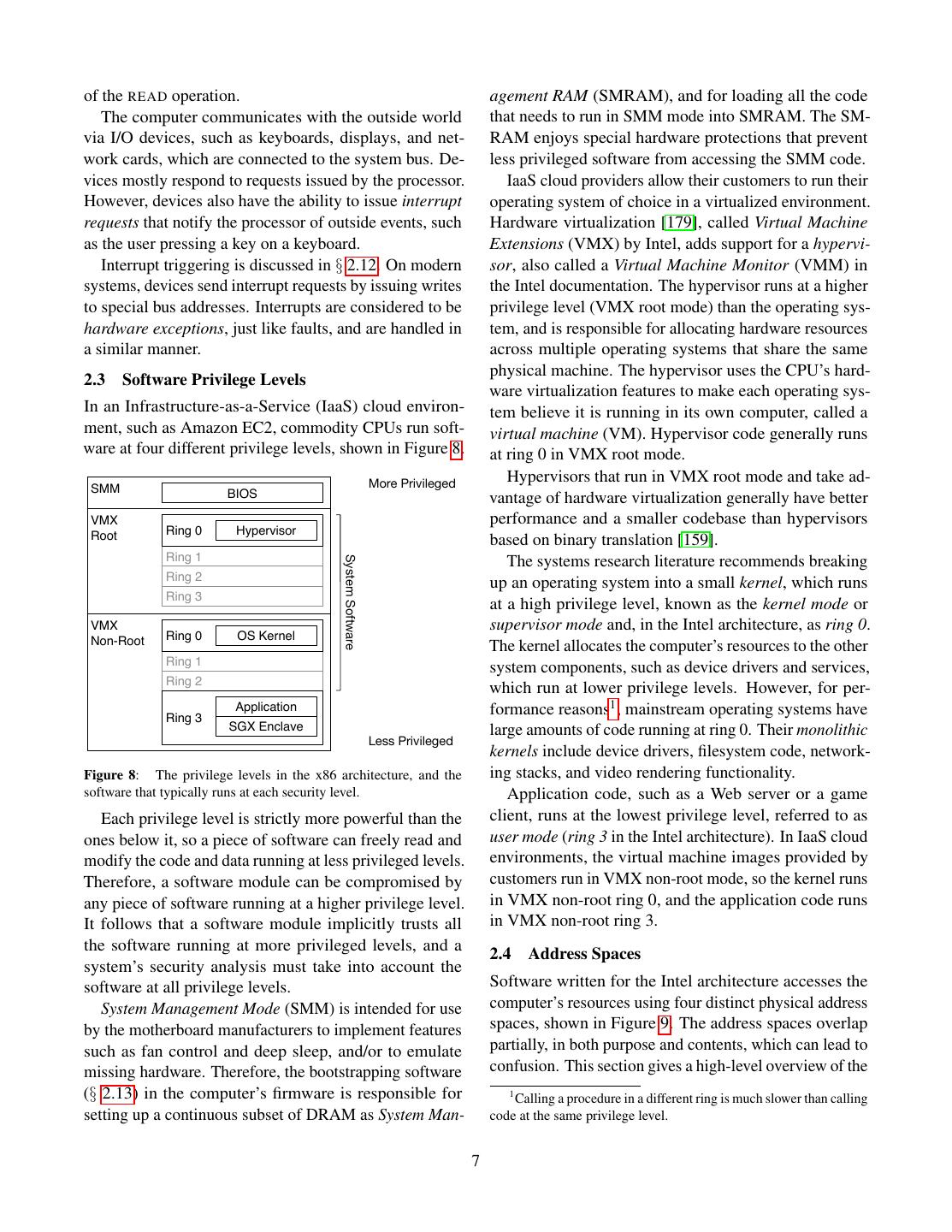
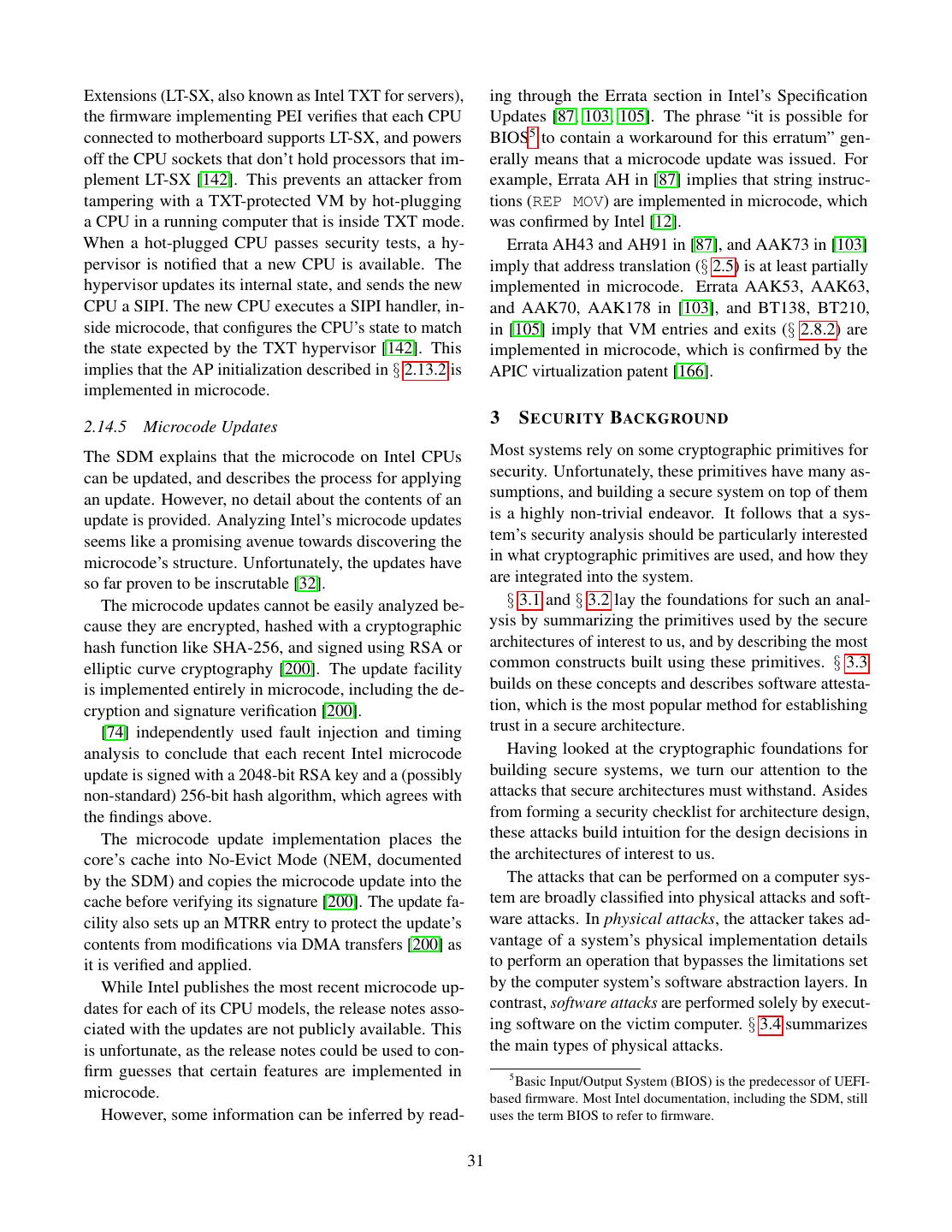
7 .of the READ operation. agement RAM (SMRAM), and for loading all the code The computer communicates with the outside world that needs to run in SMM mode into SMRAM. The SM- via I/O devices, such as keyboards, displays, and net- RAM enjoys special hardware protections that prevent work cards, which are connected to the system bus. De- less privileged software from accessing the SMM code. vices mostly respond to requests issued by the processor. IaaS cloud providers allow their customers to run their However, devices also have the ability to issue interrupt operating system of choice in a virtualized environment. requests that notify the processor of outside events, such Hardware virtualization [179], called Virtual Machine as the user pressing a key on a keyboard. Extensions (VMX) by Intel, adds support for a hypervi- Interrupt triggering is discussed in § 2.12. On modern sor, also called a Virtual Machine Monitor (VMM) in systems, devices send interrupt requests by issuing writes the Intel documentation. The hypervisor runs at a higher to special bus addresses. Interrupts are considered to be privilege level (VMX root mode) than the operating sys- hardware exceptions, just like faults, and are handled in tem, and is responsible for allocating hardware resources a similar manner. across multiple operating systems that share the same physical machine. The hypervisor uses the CPU’s hard- 2.3 Software Privilege Levels ware virtualization features to make each operating sys- In an Infrastructure-as-a-Service (IaaS) cloud environ- tem believe it is running in its own computer, called a ment, such as Amazon EC2, commodity CPUs run soft- virtual machine (VM). Hypervisor code generally runs ware at four different privilege levels, shown in Figure 8. at ring 0 in VMX root mode. More Privileged Hypervisors that run in VMX root mode and take ad- SMM BIOS vantage of hardware virtualization generally have better VMX performance and a smaller codebase than hypervisors Root Ring 0 Hypervisor based on binary translation [159]. Ring 1 System Software The systems research literature recommends breaking Ring 2 up an operating system into a small kernel, which runs Ring 3 at a high privilege level, known as the kernel mode or VMX supervisor mode and, in the Intel architecture, as ring 0. Non-Root Ring 0 OS Kernel The kernel allocates the computer’s resources to the other Ring 1 system components, such as device drivers and services, Ring 2 which run at lower privilege levels. However, for per- Ring 3 Application formance reasons1 , mainstream operating systems have SGX Enclave large amounts of code running at ring 0. Their monolithic Less Privileged kernels include device drivers, filesystem code, network- Figure 8: The privilege levels in the x86 architecture, and the ing stacks, and video rendering functionality. software that typically runs at each security level. Application code, such as a Web server or a game Each privilege level is strictly more powerful than the client, runs at the lowest privilege level, referred to as ones below it, so a piece of software can freely read and user mode (ring 3 in the Intel architecture). In IaaS cloud modify the code and data running at less privileged levels. environments, the virtual machine images provided by Therefore, a software module can be compromised by customers run in VMX non-root mode, so the kernel runs any piece of software running at a higher privilege level. in VMX non-root ring 0, and the application code runs It follows that a software module implicitly trusts all in VMX non-root ring 3. the software running at more privileged levels, and a 2.4 Address Spaces system’s security analysis must take into account the software at all privilege levels. Software written for the Intel architecture accesses the System Management Mode (SMM) is intended for use computer’s resources using four distinct physical address by the motherboard manufacturers to implement features spaces, shown in Figure 9. The address spaces overlap such as fan control and deep sleep, and/or to emulate partially, in both purpose and contents, which can lead to missing hardware. Therefore, the bootstrapping software confusion. This section gives a high-level overview of the (§ 2.13) in the computer’s firmware is responsible for 1 Calling a procedure in a different ring is much slower than calling setting up a continuous subset of DRAM as System Man- code at the same privilege level. 7
8 .physical address spaces defined by the Intel architecture, 4 GB mark) are mapped to a flash memory device that with an emphasis on their purpose and the methods used holds the first stage of the code that bootstraps the com- to manage them. puter. The memory space is partitioned between devices and CPU DRAM by the computer’s firmware during the bootstrap- MSRs ping process. Sometimes, system software includes Registers (Model-Specific Registers) motherboard-specific code that modifies the memory space partitioning. The OS kernel relies on address trans- Software lation, described in § 2.5, to control the applications’ access to the memory space. The hypervisor relies on the same mechanism to control the guest OSs. System Buses The input/output (I/O) space consists of 216 I/O ad- Memory Addresses I/O Ports dresses, usually called ports. The I/O ports are used exclusively to communicate with devices. The CPU pro- vides specific instructions for reading from and writing DRAM Device Device to the I/O space. I/O ports are allocated to devices by formal or de-facto standards. For example, ports 0xCF8 Figure 9: The four physical address spaces used by an Intel CPU. The registers and MSRs are internal to the CPU, while the memory and 0xCFC are always used to access the PCI express and I/O address spaces are used to communicate with DRAM and (§ 2.9.1) configuration space. other devices via system buses. The CPU implements a mechanism for system soft- The register space consists of names that are used to ware to provide fine-grained I/O access to applications. access the CPU’s register file, which is the only memory However, all modern kernels restrict application software that operates at the CPU’s clock frequency and can be from accessing the I/O space directly, in order to limit used without any latency penalty. The register space is the damage potential of application bugs. defined by the CPU’s architecture, and documented in The Model-Specific Register (MSR) space consists of the SDM. 232 MSRs, which are used to configure the CPU’s op- Some registers, such as the Control Registers (CRs) eration. The MSR space was initially intended for the play specific roles in configuring the CPU’s operation. use of CPU model-specific firmware, but some MSRs For example, CR3 plays a central role in address trans- have been promoted to architectural MSR status, making lation (§ 2.5). These registers can only be accessed by their semantics a part of the Intel architecture. For ex- system software. The rest of the registers make up an ample, architectural MSR 0x10 holds a high-resolution application’s execution context (§ 2.6), which is essen- monotonically increasing time-stamp counter. tially a high-speed scratch space. These registers can The CPU provides instructions for reading from and be accessed at all privilege levels, and their allocation is writing to the MSR space. The instructions can only be managed by the software’s compiler. Many CPU instruc- used by system software. Some MSRs are also exposed tions only operate on data in registers, and only place by instructions accessible to applications. For example, their results in registers. applications can read the time-stamp counter via the The memory space, generally referred to as the address RDTSC and RDTSCP instructions, which are very useful space, or the physical address space, consists of 236 for benchmarking and optimizing software. (64 GB) - 240 (1 TB) addresses. The memory space is primarily used to access DRAM, but it is also used to 2.5 Address Translation communicate with memory-mapped devices that read System software relies on the CPU’s address transla- memory requests off a system bus and write replies for tion mechanism for implementing isolation among less the CPU. Some CPU instructions can read their inputs privileged pieces of software (applications or operating from the memory space, or store the results using the systems). Virtually all secure architecture designs bring memory space. changes to address translation. We summarize the Intel A better-known example of memory mapping is that architecture’s address translation features that are most at computer startup, memory addresses 0xFFFFF000 - relevant when establishing a system’s security proper- 0xFFFFFFFF (the 64 KB of memory right below the ties, and refer the reader to [107] for a more general 8
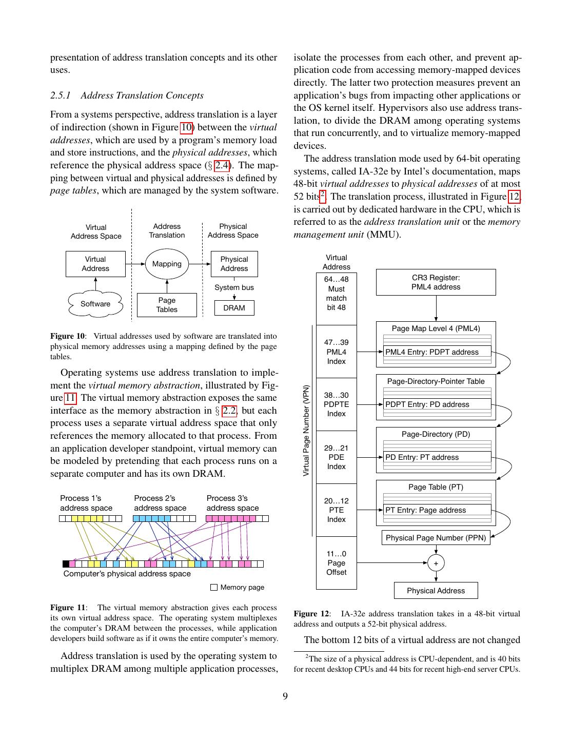
9 .presentation of address translation concepts and its other isolate the processes from each other, and prevent ap- uses. plication code from accessing memory-mapped devices directly. The latter two protection measures prevent an 2.5.1 Address Translation Concepts application’s bugs from impacting other applications or the OS kernel itself. Hypervisors also use address trans- From a systems perspective, address translation is a layer lation, to divide the DRAM among operating systems of indirection (shown in Figure 10) between the virtual that run concurrently, and to virtualize memory-mapped addresses, which are used by a program’s memory load devices. and store instructions, and the physical addresses, which The address translation mode used by 64-bit operating reference the physical address space (§ 2.4). The map- systems, called IA-32e by Intel’s documentation, maps ping between virtual and physical addresses is defined by 48-bit virtual addresses to physical addresses of at most page tables, which are managed by the system software. 52 bits2 . The translation process, illustrated in Figure 12, is carried out by dedicated hardware in the CPU, which is Virtual Address Physical referred to as the address translation unit or the memory Address Space Translation Address Space management unit (MMU). Virtual Physical Virtual Mapping Address Address Address 64…48 CR3 Register: System bus Must PML4 address Page match Software Tables DRAM bit 48 Page Map Level 4 (PML4) Figure 10: Virtual addresses used by software are translated into 47…39 physical memory addresses using a mapping defined by the page PML4 PML4 Entry: PDPT address tables. Index Operating systems use address translation to imple- Page-Directory-Pointer Table ment the virtual memory abstraction, illustrated by Fig- Virtual Page Number (VPN) (PDPT) ure 11. The virtual memory abstraction exposes the same 38…30 PDPTE PDPT Entry: PD address interface as the memory abstraction in § 2.2, but each Index process uses a separate virtual address space that only references the memory allocated to that process. From Page-Directory (PD) an application developer standpoint, virtual memory can 29…21 PDE PD Entry: PT address be modeled by pretending that each process runs on a Index separate computer and has its own DRAM. Page Table (PT) Process 1’s Process 2’s Process 3’s 20…12 address space address space address space PTE PT Entry: Page address Index Physical Page Number (PPN) 11…0 Page + Computer’s physical address space Offset Memory page Physical Address Figure 11: The virtual memory abstraction gives each process Figure 12: IA-32e address translation takes in a 48-bit virtual its own virtual address space. The operating system multiplexes address and outputs a 52-bit physical address. the computer’s DRAM between the processes, while application developers build software as if it owns the entire computer’s memory. The bottom 12 bits of a virtual address are not changed Address translation is used by the operating system to 2 The size of a physical address is CPU-dependent, and is 40 bits multiplex DRAM among multiple application processes, for recent desktop CPUs and 44 bits for recent high-end server CPUs. 9
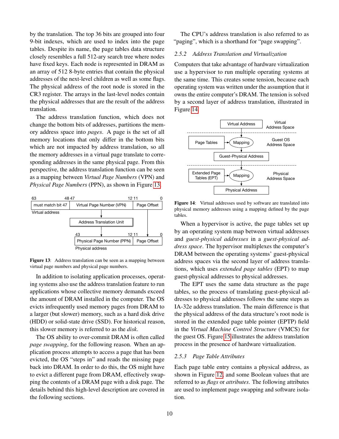
10 .by the translation. The top 36 bits are grouped into four The CPU’s address translation is also referred to as 9-bit indexes, which are used to index into the page “paging”, which is a shorthand for “page swapping”. tables. Despite its name, the page tables data structure closely resembles a full 512-ary search tree where nodes 2.5.2 Address Translation and Virtualization have fixed keys. Each node is represented in DRAM as Computers that take advantage of hardware virtualization an array of 512 8-byte entries that contain the physical use a hypervisor to run multiple operating systems at addresses of the next-level children as well as some flags. the same time. This creates some tension, because each The physical address of the root node is stored in the operating system was written under the assumption that it CR3 register. The arrays in the last-level nodes contain owns the entire computer’s DRAM. The tension is solved the physical addresses that are the result of the address by a second layer of address translation, illustrated in translation. Figure 14. The address translation function, which does not Virtual Address Virtual change the bottom bits of addresses, partitions the mem- Address Space ory address space into pages. A page is the set of all memory locations that only differ in the bottom bits Guest OS Page Tables Mapping Address Space which are not impacted by address translation, so all the memory addresses in a virtual page translate to corre- Guest-Physical Address sponding addresses in the same physical page. From this perspective, the address translation function can be seen Extended Page Mapping Physical as a mapping between Virtual Page Numbers (VPN) and Tables (EPT) Address Space Physical Page Numbers (PPN), as shown in Figure 13. Physical Address 63 48 47 12 11 0 must match bit 47 Virtual Page Number (VPN) Page Offset Figure 14: Virtual addresses used by software are translated into physical memory addresses using a mapping defined by the page Virtual address tables. Address Translation Unit When a hypervisor is active, the page tables set up 43 12 11 0 by an operating system map between virtual addresses Physical Page Number (PPN) Page Offset and guest-physical addresses in a guest-physical ad- Physical address dress space. The hypervisor multiplexes the computer’s DRAM between the operating systems’ guest-physical Figure 13: Address translation can be seen as a mapping between address spaces via the second layer of address transla- virtual page numbers and physical page numbers. tions, which uses extended page tables (EPT) to map In addition to isolating application processes, operat- guest-physical addresses to physical addresses. ing systems also use the address translation feature to run The EPT uses the same data structure as the page applications whose collective memory demands exceed tables, so the process of translating guest-physical ad- the amount of DRAM installed in the computer. The OS dresses to physical addresses follows the same steps as evicts infrequently used memory pages from DRAM to IA-32e address translation. The main difference is that a larger (but slower) memory, such as a hard disk drive the physical address of the data structure’s root node is (HDD) or solid-state drive (SSD). For historical reason, stored in the extended page table pointer (EPTP) field this slower memory is referred to as the disk. in the Virtual Machine Control Structure (VMCS) for The OS ability to over-commit DRAM is often called the guest OS. Figure 15 illustrates the address translation page swapping, for the following reason. When an ap- process in the presence of hardware virtualization. plication process attempts to access a page that has been 2.5.3 Page Table Attributes evicted, the OS “steps in” and reads the missing page back into DRAM. In order to do this, the OS might have Each page table entry contains a physical address, as to evict a different page from DRAM, effectively swap- shown in Figure 12, and some Boolean values that are ping the contents of a DRAM page with a disk page. The referred to as flags or attributes. The following attributes details behind this high-level description are covered in are used to implement page swapping and software isola- the following sections. tion. 10
11 . CR3: PDPT PD PT Guest values in these registers make up an application thread’s PML4 Physical (Guest) (Guest) (Guest) (Guest) Address state, or execution context. OS kernels multiplex each logical processor (§ 2.9.4) EPTP in EPT EPT EPT EPT EPT VMCS PML4 PML4 PML4 PML4 PML4 between multiple software threads by context switching, namely saving the values of the registers that make up a EPT EPT EPT EPT EPT thread’s execution context, and replacing them with an- PDPT PDPT PDPT PDPT PDPT other thread’s previously saved context. Context switch- EPT EPT EPT EPT EPT ing also plays a part in executing code inside secure PD PD PD PD PD containers, so its design has security implications. EPT EPT EPT EPT EPT PT PT PT PT PT 64-bit integers / pointers 64-bit special-purpose registers RAX RBX RCX RDX RIP - instruction pointer Virtual PML4 PDPT PD PT Physical RSI RDI RBP RSP RSP - stack pointer Address (Physical) (Physical) (Physical) (Physical) Address R8 R9 R10 R11 RFLAGS - status / control bits Figure 15: Address translation when hardware virtualization is R12 R13 R14 R15 enabled. The kernel-managed page tables contain guest-physical segment registers addresses, so each level in the kernel’s page table requires a full walk ignored segment registers FS GS of the hypervisor’s extended page table (EPT). A translation requires CS DS ES SS 64-bit FS base 64-bit GS base up to 20 memory accesses (the bold boxes), assuming the physical address of the kernel’s PML4 is cached. Figure 16: CPU registers in the 64-bit Intel architecture. RSP can be used as a general-purpose register (GPR), e.g., in pointer arithmetic, The present (P) flag is set to 0 to indicate unused parts but it always points to the top of the program’s stack. Segment of the address space, which do not have physical memory registers are covered in § 2.7. associated with them. The system software also sets the Integers and memory addresses are stored in 16 P flag to 0 for pages that are evicted from DRAM. When general-purpose registers (GPRs). The first 8 GPRs have the address translation unit encounters a zero P flag, it historical names: RAX, RBX, RCX, RDX, RSI, RDI, aborts the translation process and issues a hardware ex- RSP, and RBP, because they are extended versions of ception, as described in § 2.8.2. This hardware exception the 32-bit Intel architecture’s GPRs. The other 8 GPRs gives system software an opportunity to step in and bring are simply known as R9-R16. RSP is designated for an evicted page back into DRAM. pointing to the top of the procedure call stack, which is The accessed (A) flag is set to 1 by the CPU whenever simply referred to as the stack. RSP and the stack that the address translation machinery reads a page table entry, it refers to are automatically read and modified by the and the dirty (D) flag is set to 1 by the CPU when an CPU instructions that implement procedure calls, such entry is accessed by a memory write operation. The as CALL and RET (return), and by specialized stack han- A and D flags give the hypervisor and kernel insight dling instructions such as PUSH and POP. into application memory access patterns and inform the All applications also use the RIP register, which con- algorithms that select the pages that get evicted from tains the address of the currently executing instruction, RAM. and the RFLAGS register, whose bits (e.g., the carry flag The main attributes supporting software isolation are - CF) are individually used to store comparison results the writable (W) flag, which can be set to 0 to prohibit3 and control various instructions. writes to any memory location inside a page, the disable Software might use other registers to interact with execution (XD) flag, which can be set to 1 to prevent specific processor features, some of which are shown in instruction fetches from a page, and the supervisor (S) Table 1. flag, which can be set to 1 to prohibit any accesses from The Intel architecture provides a future-proof method application software running at ring 3. for an OS kernel to save the values of feature-specific 2.6 Execution Contexts registers used by an application. The XSAVE instruction takes in a requested-feature bitmap (RFBM), and writes Application software targeting the 64-bit Intel architec- the registers used by the features whose RFBM bits are ture uses a variety of CPU registers to interact with the set to 1 in a memory area. The memory area written by processor’s features, shown in Figure 16 and Table 1. The XSAVE can later be used by the XRSTOR instruction to 3 Writes to non-writable pages result in #GP exceptions (§ 2.8.2). load the saved values back into feature-specific registers. 11
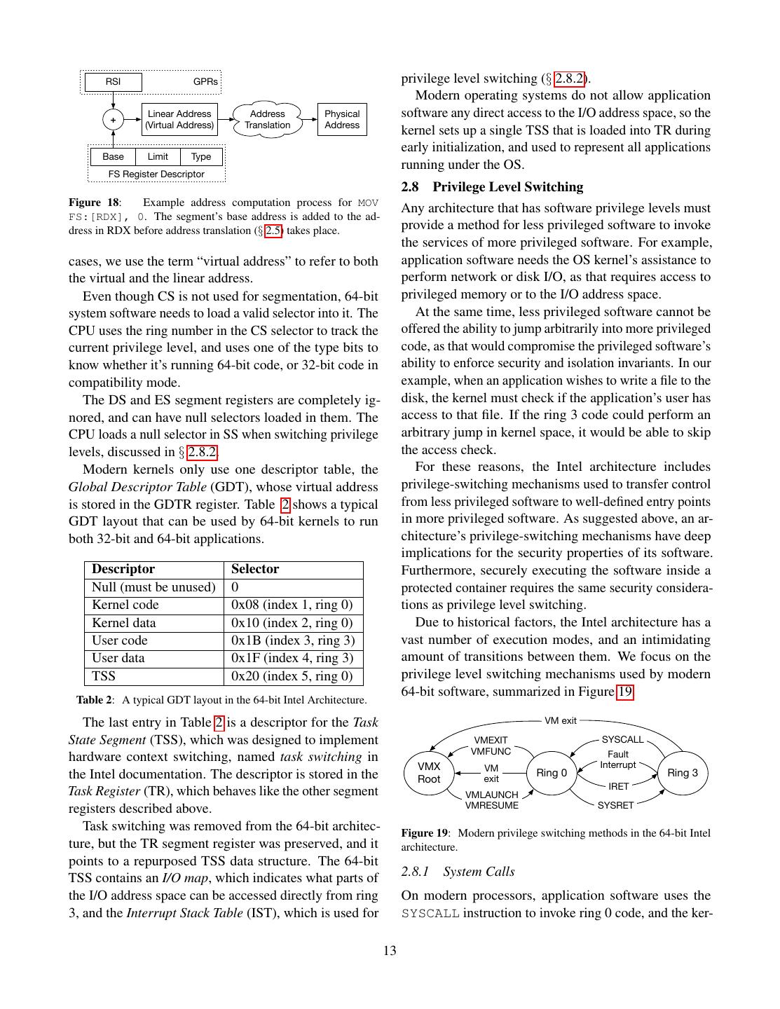
12 . Feature Registers XCR0 bit segment, which is loaded in CS, and one data segment, FPU FP0 - FP7, FSW, FTW 0 which is loaded in SS, DS and ES. The FS and GS regis- SSE MM0 - MM7, XMM0 - 1 ters store segments covering thread-local storage (TLS). XMM15, XMCSR Due to the Intel architecture’s 16-bit origins, segment AVX YMM0 - YMM15 2 registers are exposed as 16-bit values, called segment MPX BND0 - BND 3 3 selectors. The top 13 bits in a selector are an index in a MPX BNDCFGU, BNDSTATUS 4 descriptor table, and the bottom 2 bits are the selector’s AVX-512 K0 - K7 5 ring number, which is also called requested privilege AVX-512 ZMM0 H - ZMM15 H 6 level (RPL) in the Intel documentation. Also, modern AVX-512 ZMM16 - ZMM31 7 system software only uses rings 0 and 3 (see § 2.3). PK PKRU 9 Each segment register has a hidden segment descrip- tor, which consists of a base address, limit, and type Table 1: Sample feature-specific Intel architecture registers. information, such as whether the descriptor should be The memory area includes the RFBM given to XSAVE, used for executable code or data. Figure 17 shows the so XRSTOR does not require an RFBM input. effect of loading a 16-bit selector into a segment register. Application software declares the features that it plans The selector’s index is used to read a descriptor from the to use to the kernel, so the kernel knows what XSAVE descriptor table and copy it into the segment register’s bitmap to use when context-switching. When receiving hidden descriptor. the system call, the kernel sets the XCR0 register to the Input Value feature bitmap declared by the application. The CPU Index Ring GDTR generates a fault if application software attempts to use + Base Limit features that are not enabled by XCR0, so applications Descriptor Table cannot modify feature-specific registers that the kernel Base Limit Type wouldn’t take into account when context-switching. The Index Ring Base Limit Type kernel can use the CPUID instruction to learn the size of ⋮ Register Selector the XSAVE memory area for a given feature bitmap, and Base Limit Type compute how much memory it needs to allocate for the ⋮ context of each of the application’s threads. Base Limit Type 2.7 Segment Registers Base Limit Type Register Descriptor The Intel 64-bit architecture gained widespread adoption thanks to its ability to run software targeting the older 32- Figure 17: Loading a segment register. The 16-bit value loaded by bit architecture side-by-side with 64-bit software [167]. software is a selector consisting of an index and a ring number. The This ability comes at the cost of some warts. While most index selects a GDT entry, which is loaded into the descriptor part of of these warts can be ignored while reasoning about the the segment register. security of 64-bit software, the segment registers and In 64-bit mode, all segment limits are ignored. The vestigial segmentation model must be understood. base addresses in most segment registers (CS, DS, ES, The semantics of the Intel architecture’s instructions SS) are ignored. The base addresses in FS and GS are include the implicit use of a few segments which are used, in order to support thread-local storage. Figure 18 loaded into the processor’s segment registers shown in outlines the address computation in this case. The in- Figure 16. Code fetches use the code segment (CS). struction’s address, named logical address in the Intel Instructions that reference the stack implicitly use the documentation, is added to the base address in the seg- stack segment (SS). Memory references implicitly use the ment register’s descriptor, yielding the virtual address, data segment (DS) or the destination segment (ES). Via also named linear address. The virtual address is then segment override prefixes, instructions can be modified translated (§ 2.5) to a physical address. to use the unnamed segments FS and GS for memory Outside the special case of using FS or GS to refer- references. ence thread-local storage, the logical and virtual (linear) Modern operating systems effectively disable segmen- addresses match. Therefore, most of the time, we can get tation by covering the entire addressable space with one away with completely ignoring segmentation. In these 12
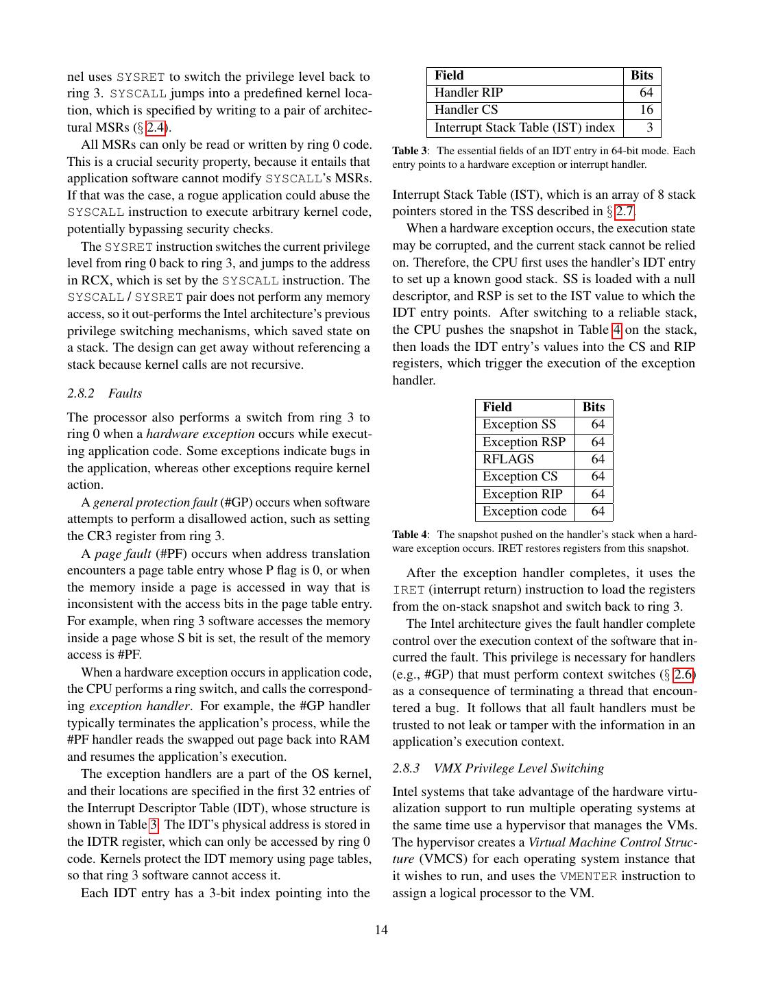
13 . RSI GPRs privilege level switching (§ 2.8.2). Modern operating systems do not allow application + Linear Address Address Physical software any direct access to the I/O address space, so the (Virtual Address) Translation Address kernel sets up a single TSS that is loaded into TR during early initialization, and used to represent all applications Base Limit Type running under the OS. FS Register Descriptor 2.8 Privilege Level Switching Figure 18: Example address computation process for MOV Any architecture that has software privilege levels must FS:[RDX], 0. The segment’s base address is added to the ad- dress in RDX before address translation (§ 2.5) takes place. provide a method for less privileged software to invoke the services of more privileged software. For example, cases, we use the term “virtual address” to refer to both application software needs the OS kernel’s assistance to the virtual and the linear address. perform network or disk I/O, as that requires access to Even though CS is not used for segmentation, 64-bit privileged memory or to the I/O address space. system software needs to load a valid selector into it. The At the same time, less privileged software cannot be CPU uses the ring number in the CS selector to track the offered the ability to jump arbitrarily into more privileged current privilege level, and uses one of the type bits to code, as that would compromise the privileged software’s know whether it’s running 64-bit code, or 32-bit code in ability to enforce security and isolation invariants. In our compatibility mode. example, when an application wishes to write a file to the The DS and ES segment registers are completely ig- disk, the kernel must check if the application’s user has nored, and can have null selectors loaded in them. The access to that file. If the ring 3 code could perform an CPU loads a null selector in SS when switching privilege arbitrary jump in kernel space, it would be able to skip levels, discussed in § 2.8.2. the access check. Modern kernels only use one descriptor table, the For these reasons, the Intel architecture includes Global Descriptor Table (GDT), whose virtual address privilege-switching mechanisms used to transfer control is stored in the GDTR register. Table 2 shows a typical from less privileged software to well-defined entry points GDT layout that can be used by 64-bit kernels to run in more privileged software. As suggested above, an ar- both 32-bit and 64-bit applications. chitecture’s privilege-switching mechanisms have deep implications for the security properties of its software. Descriptor Selector Furthermore, securely executing the software inside a Null (must be unused) 0 protected container requires the same security considera- Kernel code 0x08 (index 1, ring 0) tions as privilege level switching. Kernel data 0x10 (index 2, ring 0) Due to historical factors, the Intel architecture has a User code 0x1B (index 3, ring 3) vast number of execution modes, and an intimidating User data 0x1F (index 4, ring 3) amount of transitions between them. We focus on the TSS 0x20 (index 5, ring 0) privilege level switching mechanisms used by modern 64-bit software, summarized in Figure 19. Table 2: A typical GDT layout in the 64-bit Intel Architecture. The last entry in Table 2 is a descriptor for the Task VM exit State Segment (TSS), which was designed to implement VMEXIT SYSCALL VMFUNC Fault hardware context switching, named task switching in Interrupt VMX VM the Intel documentation. The descriptor is stored in the Ring 0 Ring 3 Root exit IRET Task Register (TR), which behaves like the other segment VMLAUNCH registers described above. VMRESUME SYSRET Task switching was removed from the 64-bit architec- Figure 19: Modern privilege switching methods in the 64-bit Intel ture, but the TR segment register was preserved, and it architecture. points to a repurposed TSS data structure. The 64-bit TSS contains an I/O map, which indicates what parts of 2.8.1 System Calls the I/O address space can be accessed directly from ring On modern processors, application software uses the 3, and the Interrupt Stack Table (IST), which is used for SYSCALL instruction to invoke ring 0 code, and the ker- 13
14 .nel uses SYSRET to switch the privilege level back to Field Bits ring 3. SYSCALL jumps into a predefined kernel loca- Handler RIP 64 tion, which is specified by writing to a pair of architec- Handler CS 16 tural MSRs (§ 2.4). Interrupt Stack Table (IST) index 3 All MSRs can only be read or written by ring 0 code. Table 3: The essential fields of an IDT entry in 64-bit mode. Each This is a crucial security property, because it entails that entry points to a hardware exception or interrupt handler. application software cannot modify SYSCALL’s MSRs. If that was the case, a rogue application could abuse the Interrupt Stack Table (IST), which is an array of 8 stack SYSCALL instruction to execute arbitrary kernel code, pointers stored in the TSS described in § 2.7. potentially bypassing security checks. When a hardware exception occurs, the execution state The SYSRET instruction switches the current privilege may be corrupted, and the current stack cannot be relied level from ring 0 back to ring 3, and jumps to the address on. Therefore, the CPU first uses the handler’s IDT entry in RCX, which is set by the SYSCALL instruction. The to set up a known good stack. SS is loaded with a null SYSCALL / SYSRET pair does not perform any memory descriptor, and RSP is set to the IST value to which the access, so it out-performs the Intel architecture’s previous IDT entry points. After switching to a reliable stack, privilege switching mechanisms, which saved state on the CPU pushes the snapshot in Table 4 on the stack, a stack. The design can get away without referencing a then loads the IDT entry’s values into the CS and RIP stack because kernel calls are not recursive. registers, which trigger the execution of the exception handler. 2.8.2 Faults Field Bits The processor also performs a switch from ring 3 to Exception SS 64 ring 0 when a hardware exception occurs while execut- Exception RSP 64 ing application code. Some exceptions indicate bugs in RFLAGS 64 the application, whereas other exceptions require kernel Exception CS 64 action. Exception RIP 64 A general protection fault (#GP) occurs when software Exception code 64 attempts to perform a disallowed action, such as setting the CR3 register from ring 3. Table 4: The snapshot pushed on the handler’s stack when a hard- ware exception occurs. IRET restores registers from this snapshot. A page fault (#PF) occurs when address translation encounters a page table entry whose P flag is 0, or when After the exception handler completes, it uses the the memory inside a page is accessed in way that is IRET (interrupt return) instruction to load the registers inconsistent with the access bits in the page table entry. from the on-stack snapshot and switch back to ring 3. For example, when ring 3 software accesses the memory The Intel architecture gives the fault handler complete inside a page whose S bit is set, the result of the memory control over the execution context of the software that in- access is #PF. curred the fault. This privilege is necessary for handlers When a hardware exception occurs in application code, (e.g., #GP) that must perform context switches (§ 2.6) the CPU performs a ring switch, and calls the correspond- as a consequence of terminating a thread that encoun- ing exception handler. For example, the #GP handler tered a bug. It follows that all fault handlers must be typically terminates the application’s process, while the trusted to not leak or tamper with the information in an #PF handler reads the swapped out page back into RAM application’s execution context. and resumes the application’s execution. The exception handlers are a part of the OS kernel, 2.8.3 VMX Privilege Level Switching and their locations are specified in the first 32 entries of Intel systems that take advantage of the hardware virtu- the Interrupt Descriptor Table (IDT), whose structure is alization support to run multiple operating systems at shown in Table 3. The IDT’s physical address is stored in the same time use a hypervisor that manages the VMs. the IDTR register, which can only be accessed by ring 0 The hypervisor creates a Virtual Machine Control Struc- code. Kernels protect the IDT memory using page tables, ture (VMCS) for each operating system instance that so that ring 3 software cannot access it. it wishes to run, and uses the VMENTER instruction to Each IDT entry has a 3-bit index pointing into the assign a logical processor to the VM. 14
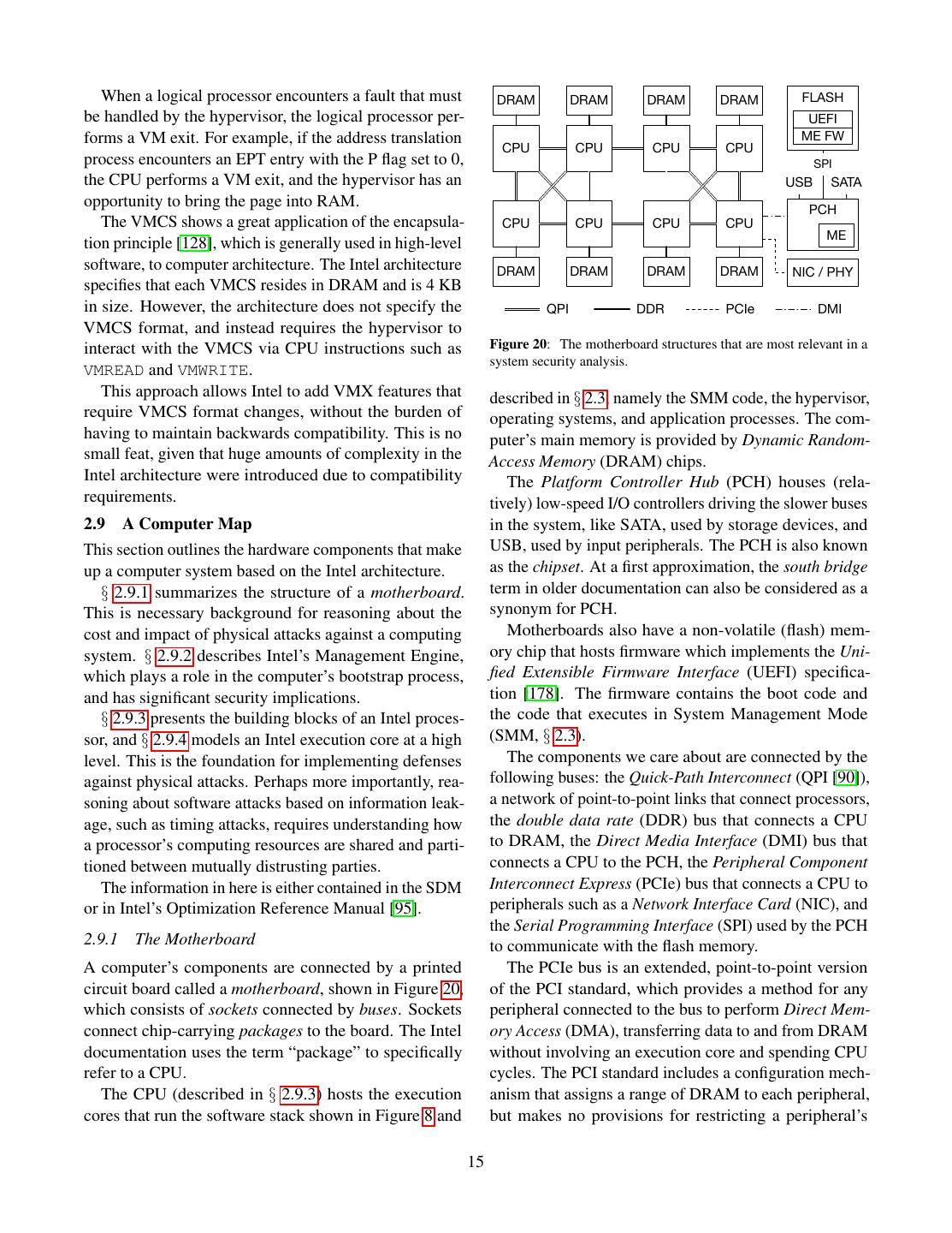
15 . When a logical processor encounters a fault that must DRAM DRAM DRAM DRAM FLASH be handled by the hypervisor, the logical processor per- UEFI forms a VM exit. For example, if the address translation ME FW CPU CPU CPU CPU process encounters an EPT entry with the P flag set to 0, SPI the CPU performs a VM exit, and the hypervisor has an USB SATA opportunity to bring the page into RAM. PCH The VMCS shows a great application of the encapsula- CPU CPU CPU CPU ME tion principle [128], which is generally used in high-level software, to computer architecture. The Intel architecture DRAM DRAM DRAM DRAM NIC / PHY specifies that each VMCS resides in DRAM and is 4 KB in size. However, the architecture does not specify the QPI DDR PCIe DMI VMCS format, and instead requires the hypervisor to interact with the VMCS via CPU instructions such as Figure 20: The motherboard structures that are most relevant in a system security analysis. VMREAD and VMWRITE. This approach allows Intel to add VMX features that described in § 2.3, namely the SMM code, the hypervisor, require VMCS format changes, without the burden of operating systems, and application processes. The com- having to maintain backwards compatibility. This is no puter’s main memory is provided by Dynamic Random- small feat, given that huge amounts of complexity in the Access Memory (DRAM) chips. Intel architecture were introduced due to compatibility The Platform Controller Hub (PCH) houses (rela- requirements. tively) low-speed I/O controllers driving the slower buses 2.9 A Computer Map in the system, like SATA, used by storage devices, and This section outlines the hardware components that make USB, used by input peripherals. The PCH is also known up a computer system based on the Intel architecture. as the chipset. At a first approximation, the south bridge § 2.9.1 summarizes the structure of a motherboard. term in older documentation can also be considered as a This is necessary background for reasoning about the synonym for PCH. cost and impact of physical attacks against a computing Motherboards also have a non-volatile (flash) mem- system. § 2.9.2 describes Intel’s Management Engine, ory chip that hosts firmware which implements the Uni- which plays a role in the computer’s bootstrap process, fied Extensible Firmware Interface (UEFI) specifica- and has significant security implications. tion [178]. The firmware contains the boot code and § 2.9.3 presents the building blocks of an Intel proces- the code that executes in System Management Mode sor, and § 2.9.4 models an Intel execution core at a high (SMM, § 2.3). level. This is the foundation for implementing defenses The components we care about are connected by the against physical attacks. Perhaps more importantly, rea- following buses: the Quick-Path Interconnect (QPI [90]), soning about software attacks based on information leak- a network of point-to-point links that connect processors, age, such as timing attacks, requires understanding how the double data rate (DDR) bus that connects a CPU a processor’s computing resources are shared and parti- to DRAM, the Direct Media Interface (DMI) bus that tioned between mutually distrusting parties. connects a CPU to the PCH, the Peripheral Component The information in here is either contained in the SDM Interconnect Express (PCIe) bus that connects a CPU to or in Intel’s Optimization Reference Manual [95]. peripherals such as a Network Interface Card (NIC), and the Serial Programming Interface (SPI) used by the PCH 2.9.1 The Motherboard to communicate with the flash memory. A computer’s components are connected by a printed The PCIe bus is an extended, point-to-point version circuit board called a motherboard, shown in Figure 20, of the PCI standard, which provides a method for any which consists of sockets connected by buses. Sockets peripheral connected to the bus to perform Direct Mem- connect chip-carrying packages to the board. The Intel ory Access (DMA), transferring data to and from DRAM documentation uses the term “package” to specifically without involving an execution core and spending CPU refer to a CPU. cycles. The PCI standard includes a configuration mech- The CPU (described in § 2.9.3) hosts the execution anism that assigns a range of DRAM to each peripheral, cores that run the software stack shown in Figure 8 and but makes no provisions for restricting a peripheral’s 15
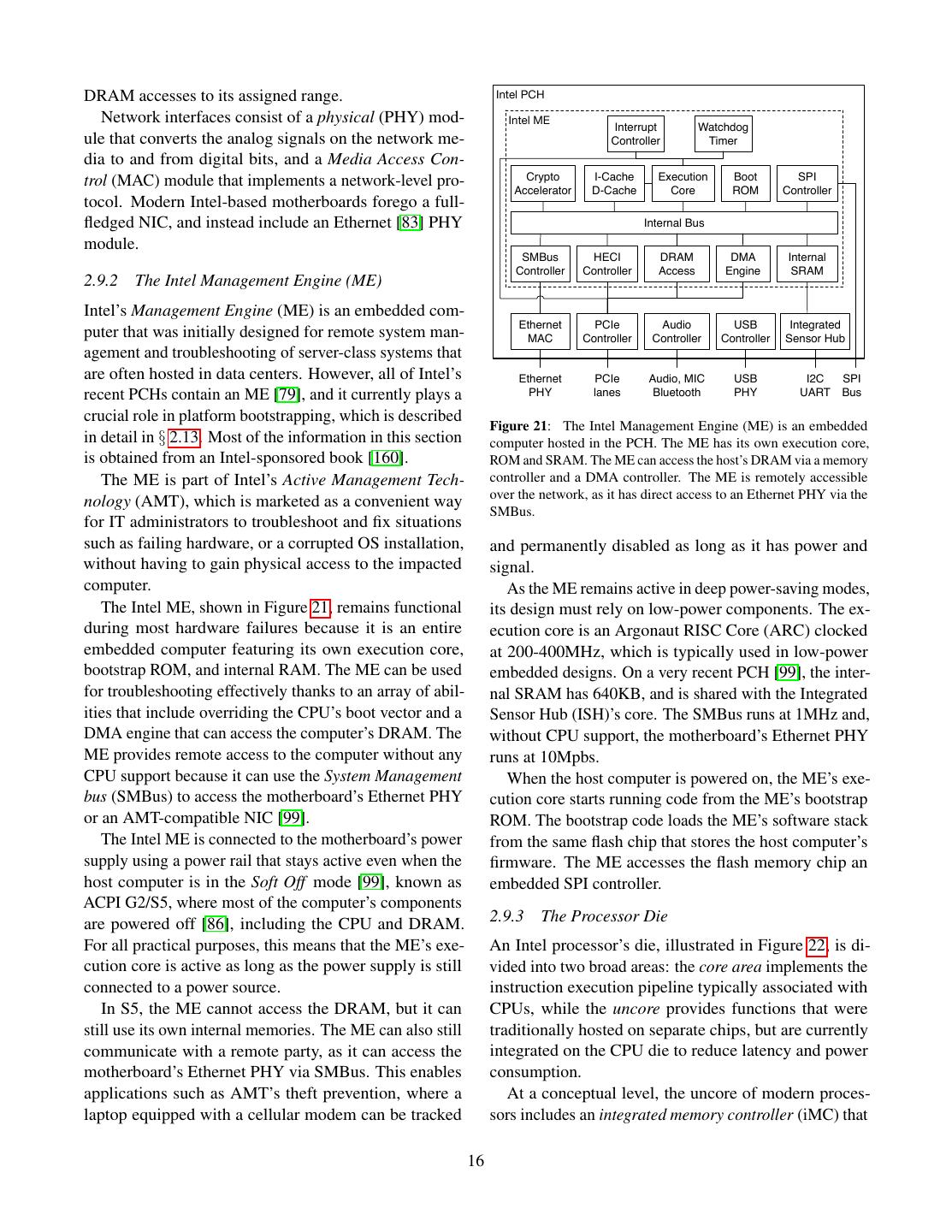
16 .DRAM accesses to its assigned range. Intel PCH Network interfaces consist of a physical (PHY) mod- Intel ME Interrupt Watchdog ule that converts the analog signals on the network me- Controller Timer dia to and from digital bits, and a Media Access Con- trol (MAC) module that implements a network-level pro- Crypto I-Cache Execution Boot SPI Accelerator D-Cache Core ROM Controller tocol. Modern Intel-based motherboards forego a full- fledged NIC, and instead include an Ethernet [83] PHY Internal Bus module. SMBus HECI DRAM DMA Internal Controller Controller Access Engine SRAM 2.9.2 The Intel Management Engine (ME) Intel’s Management Engine (ME) is an embedded com- Ethernet PCIe Audio USB Integrated puter that was initially designed for remote system man- MAC Controller Controller Controller Sensor Hub agement and troubleshooting of server-class systems that are often hosted in data centers. However, all of Intel’s Ethernet PCIe Audio, MIC USB I2C SPI recent PCHs contain an ME [79], and it currently plays a PHY lanes Bluetooth PHY UART Bus crucial role in platform bootstrapping, which is described Figure 21: The Intel Management Engine (ME) is an embedded in detail in § 2.13. Most of the information in this section computer hosted in the PCH. The ME has its own execution core, is obtained from an Intel-sponsored book [160]. ROM and SRAM. The ME can access the host’s DRAM via a memory The ME is part of Intel’s Active Management Tech- controller and a DMA controller. The ME is remotely accessible over the network, as it has direct access to an Ethernet PHY via the nology (AMT), which is marketed as a convenient way SMBus. for IT administrators to troubleshoot and fix situations such as failing hardware, or a corrupted OS installation, and permanently disabled as long as it has power and without having to gain physical access to the impacted signal. computer. As the ME remains active in deep power-saving modes, The Intel ME, shown in Figure 21, remains functional its design must rely on low-power components. The ex- during most hardware failures because it is an entire ecution core is an Argonaut RISC Core (ARC) clocked embedded computer featuring its own execution core, at 200-400MHz, which is typically used in low-power bootstrap ROM, and internal RAM. The ME can be used embedded designs. On a very recent PCH [99], the inter- for troubleshooting effectively thanks to an array of abil- nal SRAM has 640KB, and is shared with the Integrated ities that include overriding the CPU’s boot vector and a Sensor Hub (ISH)’s core. The SMBus runs at 1MHz and, DMA engine that can access the computer’s DRAM. The without CPU support, the motherboard’s Ethernet PHY ME provides remote access to the computer without any runs at 10Mpbs. CPU support because it can use the System Management When the host computer is powered on, the ME’s exe- bus (SMBus) to access the motherboard’s Ethernet PHY cution core starts running code from the ME’s bootstrap or an AMT-compatible NIC [99]. ROM. The bootstrap code loads the ME’s software stack The Intel ME is connected to the motherboard’s power from the same flash chip that stores the host computer’s supply using a power rail that stays active even when the firmware. The ME accesses the flash memory chip an host computer is in the Soft Off mode [99], known as embedded SPI controller. ACPI G2/S5, where most of the computer’s components are powered off [86], including the CPU and DRAM. 2.9.3 The Processor Die For all practical purposes, this means that the ME’s exe- An Intel processor’s die, illustrated in Figure 22, is di- cution core is active as long as the power supply is still vided into two broad areas: the core area implements the connected to a power source. instruction execution pipeline typically associated with In S5, the ME cannot access the DRAM, but it can CPUs, while the uncore provides functions that were still use its own internal memories. The ME can also still traditionally hosted on separate chips, but are currently communicate with a remote party, as it can access the integrated on the CPU die to reduce latency and power motherboard’s Ethernet PHY via SMBus. This enables consumption. applications such as AMT’s theft prevention, where a At a conceptual level, the uncore of modern proces- laptop equipped with a cellular modem can be tracked sors includes an integrated memory controller (iMC) that 16
17 . NIC Platform Controller Hub Logical CPU Logical CPU L1 L1 Registers Registers Fetch PCI-X DMI I-Cache I-TLB LAPIC LAPIC Chip Package Decode Microcode IOAPIC I/O Controller Core Core Graphics Instruction Scheduler L2 L2 CPU I/O to Ring Unit Cache TLB Config L3 Cache Power L1 L1 QPI Router Home Agent INT INT INT MEM Unit D-Cache D-TLB QPI Memory FP FP SSE SSE Core Core Page Miss Handler (PMH) Packetizer Controller Execution Units QPI DDR3 Figure 23: CPU core with two logical processors. Each logical CPU DRAM processor has its own execution context and LAPIC (§ 2.12). All the other core resources are shared. Figure 22: The major components in a modern CPU package. § 2.9.3 gives an uncore overview. § 2.9.4 describes execution cores. A hyper-threaded core is exposed to system software § 2.11.3 takes a deeper look at the uncore. as two logical processors (LPs), also named hardware threads in the Intel documentation. The logical proces- interfaces with the DDR bus, an integrated I/O controller sor abstraction allows the code used to distribute work (IIO) that implements PCIe bus lanes and interacts with across processors in a multi-processor system to func- the DMI bus, and a growing number of integrated pe- tion without any change on multi-core hyper-threaded ripherals, such as a Graphics Processing Unit (GPU). processors. The uncore structure is described in some processor fam- The high level of resource sharing introduced by ily datasheets [96, 97], and in the overview sections in hyper-threading introduces a security vulnerability. Soft- Intel’s uncore performance monitoring documentation ware running on one logical processor can use the high- [37, 89, 93]. resolution performance counter (RDTSCP, § 2.4) [150] Security extensions to the Intel architecture, such as to get information about the instructions and memory ac- Trusted Execution Technology (TXT) [70] and Software cess patterns of another piece of software that is executed Guard Extensions (SGX) [14, 137], rely on the fact that on the other logical processor on the same core. the processor die includes the memory and I/O controller, That being said, the biggest downside of hyper- and thus can prevent any device from accessing protected threading might be the fact that writing about Intel pro- memory areas via Direct Memory Access (DMA) trans- cessors in a rigorous manner requires the use of the cum- fers. § 2.11.3 takes a deeper look at the uncore organiza- bersome term Logical Processor instead of the shorter tion and at the machinery used to prevent unauthorized and more intuitive “CPU core”, which can often be ab- DMA transfers. breviated to “core”. 2.9.4 The Core 2.10 Out-of-Order and Speculative Execution Virtually all modern Intel processors have core areas con- CPU cores can execute instructions orders of magni- sisting of multiple copies of the execution core circuitry, tude faster than DRAM can read data. Computer archi- each of which is called a core. At the time of this writing, tects attempt to bridge this gap by using hyper-threading desktop-class Intel CPUs have 4 cores, and server-class (§ 2.9.3), out-of-order and speculative execution, and CPUs have as many as 18 cores. caching, which is described in § 2.11. In CPUs that Most Intel CPUs feature hyper-threading, which use out-of-order execution, the order in which the CPU means that a core (shown in Figure 23) has two copies carries out a program’s instructions (execution order) is of the register files backing the execution context de- not necessarily the same as the order in which the in- scribed in § 2.6, and can execute two separate streams of structions would be executed by a sequential evaluation instructions simultaneously. Hyper-threading reduces the system (program order). impact of memory stalls on the utilization of the fetch, An analysis of a system’s information leakage must decode and execution units. take out-of-order execution into consideration. Any CPU 17
18 .actions observed by an attacker match the execution The Intel architecture defines a complex instruction order, so the attacker may learn some information by set (CISC). However, virtually all modern CPUs are ar- comparing the observed execution order with a known chitected following reduced instruction set (RISC) prin- program order. At the same time, attacks that try to infer ciples. This is accomplished by having the instruction a victim’s program order based on actions taken by the decode stages break down each instruction into micro- CPU must account for out-of-order execution as a source ops, which resemble RISC instructions. The other stages of noise. of the execution pipeline work exclusively with micro- This section summarizes the out-of-order and specu- ops. lative execution concepts used when reasoning about a system’s security properties. [148] and [75] cover the 2.10.1 Out-of-Order Execution concepts in great depth, while Intel’s optimization man- Different types of instructions require different logic ual [95] provides details specific to Intel CPUs. circuits, called functional units. For example, the arith- Figure 24 provides a more detailed view of the CPU metic logic unit (ALU), which performs arithmetic op- core components involved in out-of-order execution, and erations, is completely different from the load and store omits some less relevant details from Figure 23. unit, which performs memory operations. Different cir- cuits can be used at the same time, so each CPU core can Branch Instruction L1 I-Cache execute multiple micro-ops in parallel. Predictors Fetch Unit L1 I-TLB The core’s out-of-order engine receives decoded Pre-Decode Fetch Buffer micro-ops, identifies the micro-ops that can execute in Instruction Queue parallel, assigns them to functional units, and combines Microcode Complex Simple the outputs of the units so that the results are equiva- ROM Decoder Decoders lent to having the micro-ops executed sequentially in the Micro-op Micro-op Decode Queue order in which they come from the decode stages. Cache Instruction Decode For example, consider the sequence of pseudo micro- Out of Order Engine ops4 in Table 5 below. The OR uses the result of the Register Reorder Load Store Files Buffer Buffer Buffer LOAD, but the ADD does not. Therefore, a good scheduler can have the load store unit execute the LOAD and the Renamer ALU execute the ADD, all in the same clock cycle. Scheduler Reservation Station # Micro-op Meaning Port 0 Port 1 Ports 2, 3 Port 4 Port 5 Port 6 Port 7 1 LOAD RAX, RSI RAX ← DRAM[RSI] Integer ALU Shift Integer ALU LEA Load & Store Store Data Integer ALU LEA Integer ALU Shift Store Address 2 OR RDI, RDI, RAX RDI ← RDI ∨ RAX FMA FMA Address Vector Branch 3 ADD RSI, RSI, RCX RSI ← RSI + RCX FP Multiply FP Multiply Shuffle 4 SUB RBX, RSI, RDX RBX ← RSI - RDX Integer Integer Integer Vector Vector Vector Table 5: Pseudo micro-ops for the out-of-order execution example. Multiply ALU ALU Vector Logicals Vector Logicals Vector Logicals The out-of-order engine in recent Intel CPUs works Branch FP Addition roughly as follows. Micro-ops received from the decode Divide queue are written into a reorder buffer (ROB) while they Vector Shift are in-flight in the execution unit. The register allocation Execution table (RAT) matches each register with the last reorder Memory Control buffer entry that updates it. The renamer uses the RAT to rewrite the source and destination fields of micro-ops L1 D-Cache Fill Buffers L2 D-Cache when they are written in the ROB, as illustrated in Tables L1 D-TLB Memory 6 and 7. Note that the ROB representation makes it easy to determine the dependencies between micro-ops. Figure 24: The structures in a CPU core that are relevant to out- of-order and speculative execution. Instructions are decoded into 4 The set of micro-ops used by Intel CPUs is not publicly docu- micro-ops, which are scheduled on one of the execution unit’s ports. mented. The fictional examples in this section suffice for illustration The branch predictor enables speculative execution when a branch is purposes. encountered. 18
19 . # Op Source 1 Source 2 Destination The most well-known branching instructions in the Intel 1 LOAD RSI ∅ RAX architecture are in the jcc family, such as je (jump if 2 OR RDI ROB #1 RSI equal). 3 ADD RSI RCX RSI Branches pose a challenge to the decode stage, because 4 SUB ROB # 3 RDX RBX the instruction that should be fetched after a branch is Table 6: Data written by the renamer into the reorder buffer (ROB), not known until the branching condition is evaluated. In for the micro-ops in Table 5. order to avoid stalling the decode stage, modern CPU Register RAX RBX RCX RDX RSI RDI designs include branch predictors that use historical in- ROB # #1 #4 ∅ ∅ #3 #2 formation to guess whether a branch will be taken or not. Table 7: Relevant entries of the register allocation table after the When the decode stage encounters a branch instruc- micro-ops in Table 5 are inserted into the ROB. tion, it asks the branch predictor for a guess as to whether The scheduler decides which micro-ops in the ROB the branch will be taken or not. The decode stage bun- get executed, and places them in the reservation station. dles the branch condition and the predictor’s guess into The reservation station has one port for each functional a branch check micro-op, and then continues decoding unit that can execute micro-ops independently. Each on the path indicated by the predictor. The micro-ops reservation station port port holds one micro-op from following the branch check are marked as speculative. the ROB. The reservation station port waits until the When the branch check micro-op is executed, the micro-op’s dependencies are satisfied and forwards the branch unit checks whether the branch predictor’s guess micro-op to the functional unit. When the functional unit was correct. If that is the case, the branch check is retired completes executing the micro-op, its result is written successfully. The scheduler handles mispredictions by back to the ROB, and forwarded to any other reservation squashing all the micro-ops following the branch check, station port that depends on it. and by signaling the instruction decoder to flush the The ROB stores the results of completed micro-ops un- micro-op decode queue and start fetching the instruc- til they are retired, meaning that the results are committed tions that follow the correct branch. to the register file and the micro-ops are removed from Modern CPUs also attempt to predict memory read pat- the ROB. Although micro-ops can be executed out-of- terns, so they can prefetch the memory locations that are order, they must be retired in program order, in order to about to be read into the cache. Prefetching minimizes handle exceptions correctly. When a micro-op causes a the latency of successfully predicted read operations, as hardware exception (§ 2.8.2), all the following micro-ops their data will already be cached. This is accomplished in the ROB are squashed, and their results are discarded. by exposing circuits called prefetchers to memory ac- In the example above, the ADD can complete before cesses and cache misses. Each prefetcher can recognize the LOAD, because it does not require a memory access. a particular access pattern, such as sequentially read- However, the ADD’s result cannot be committed before ing an array’s elements. When memory accesses match LOAD completes. Otherwise, if the ADD is committed the pattern that a prefetcher was built to recognize, the and the LOAD causes a page fault, software will observe prefetcher loads the cache line corresponding to the next an incorrect value for the RSI register. memory access in its pattern. The ROB is tailored for discovering register dependen- 2.11 Cache Memories cies between micro-ops. However, micro-ops that exe- cute out-of-order can also have memory dependencies. At the time of this writing, CPU cores can process data For this reason, out-of-order engines have a load buffer ≈ 200× faster than DRAM can supply it. This gap is and a store buffer that keep track of in-flight memory op- bridged by an hierarchy of cache memories, which are erations and are used to resolve memory dependencies. orders of magnitude smaller and an order of magnitude faster than DRAM. While caching is transparent to ap- 2.10.2 Speculative Execution plication software, the system software is responsible for Branch instructions, also called branches, change the managing and coordinating the caches that store address instruction pointer (RIP, § 2.6), if a condition is met (the translation (§ 2.5) results. branch is taken). They implement conditional statements Caches impact the security of a software system in (if) and looping statements, such as while and for. two ways. First, the Intel architecture relies on system 19
20 .software to manage address translation caches, which Look for a cache Cache line storing A Lookup becomes an issue in a threat model where the system soft- ware is untrusted. Second, caches in the Intel architecture are shared by all the software running on the computer. YES NO Look for a free cache Found? hit miss line that can store A This opens up the way for cache timing attacks, an entire class of software attacks that rely on observing the time differences between accessing a cached memory location YES Found? and an uncached memory location. NO This section summarizes the caching concepts and im- plementation details needed to reason about both classes Cache Eviction Choose a cache line of security problems mentioned above. [168], [148] and that can store A [75] provide a good background on low-level cache im- plementation concepts. § 3.8 describes cache timing NO Is the line dirty? attacks. YES 2.11.1 Caching Principles Mark the line Write the cache line At a high level, caches exploit the high locality in the available to the next level memory access patterns of most applications to hide the main memory’s (relatively) high latency. By caching Cache (storing a copy of) the most recently accessed code and Get A from the Store the data at A Fill next memory level in the free line data, these relatively small memories can be used to satisfy 90%-99% of an application’s memory accesses. In an Intel processor, the first-level (L1) cache consists Return data of a separate data cache (D-cache) and an instruction associated with A cache (I-cache). The instruction fetch and decode stage Figure 25: The steps taken by a cache memory to resolve an access is directly connected to the L1 I-cache, and uses it to read to a memory address A. A normal memory access (to cacheable the streams of instructions for the core’s logical proces- DRAM) always triggers a cache lookup. If the access misses the sors. Micro-ops that read from or write to memory are cache, a fill is required, and a write-back might be required. executed by the memory unit (MEM in Figure 23), which is connected to the L1 D-cache and forwards memory the L3 cache is in the CPU’s uncore (see Figure 22), and accesses to it. is shared by all the cores in the package. Figure 25 illustrates the steps taken by a cache when it The numbers in Table 8 suggest that cache placement receives a memory access. First, a cache lookup uses the can have a large impact on an application’s execution memory address to determine if the corresponding data time. Because of this, the Intel architecture includes exists in the cache. A cache hit occurs when the address an assortment of instructions that give performance- is found, and the cache can resolve the memory access sensitive applications some control over the caching quickly. Conversely, if the address is not found, a cache of their working sets. PREFETCH instructs the CPU’s miss occurs, and a cache fill is required to resolve the prefetcher to cache a specific memory address, in prepa- memory access. When doing a fill, the cache forwards ration for a future memory access. The memory writes the memory access to the next level of the memory hierar- performed by the MOVNT instruction family bypass the chy and caches the response. Under most circumstances, cache if a fill would be required. CLFLUSH evicts any a cache fill also triggers a cache eviction, in which some cache lines storing a specific address from the entire data is removed from the cache to make room for the cache hierarchy. data coming from the fill. If the data that is evicted has The methods mentioned above are available to soft- been modified since it was loaded in the cache, it must be ware running at all privilege levels, because they were de- written back to the next level of the memory hierarchy. signed for high-performance workloads with large work- Table 8 shows the key characteristics of the memory ing sets, which are usually executed at ring 3 (§ 2.3). For hierarchy implemented by modern Intel CPUs. Each comparison, the instructions used by system software core has its own L1 and L2 cache (see Figure 23), while to manage the address translation caches, described in 20
21 . Memory Size Access Time Memory Address Core Registers 1 KB no latency Address Tag Set Index Line Offset n-1…s+l s+l-1…l l-1…0 L1 D-Cache 32 KB 4 cycles L2 Cache 256 KB 10 cycles L3 Cache 8 MB 40-75 cycles Set 0, Way 0 Set 0, Way 1 … Set 0, Way W-1 DRAM 16 GB 60 ns Set 1, Way 0 Set 1, Way 1 … Set 1, Way W-1 Table 8: Approximate sizes and access times for each level in the ⋮ ⋮ ⋱ ⋮ memory hierarchy of an Intel processor, from [125]. Memory sizes Set i, Way 0 Set i, Way 1 … Set i, Way W-1 and access times differ by orders of magnitude across the different ⋮ ⋮ ⋱ ⋮ levels of the hierarchy. This table does not cover multi-processor Set S-1, Way 0 Set S-1, Way 1 … Set S-1, Way W-1 systems. § 2.11.5 below, can only be executed at ring 0. Way 0 Way 1 … Way W-1 Tag Line Tag Line Tag Line 2.11.2 Cache Organization In the Intel architecture, caches are completely imple- mented in hardware, meaning that the software stack has Tag Comparator no direct control over the eviction process. However, software can gain some control over which data gets Matched Line evicted by understanding how the caches are organized, and by cleverly placing its data in memory. Match? Matched Word The cache line is the atomic unit of cache organization. Figure 26: Cache organization and lookup, for a W -way set- A cache line has data, a copy of a continuous range of associative cache with 2l -byte lines and S = 2s sets. The cache DRAM, and a tag, identifying the memory address that works with n-bit memory addresses. The lowest l address bits point the data comes from. Fills and evictions operate on entire to a specific byte in a cache line, the next s bytes index the set, and lines. the highest n − s − l bits are used to decide if the desired address is in one of the W lines in the indexed set. The cache line size is the size of the data, and is always a power of two. Assuming n-bit memory addresses and a 2.11.3 Cache Coherence cache line size of 2l bytes, the lowest l bits of a memory address are an offset into a cache line, and the highest The Intel architecture was designed to support applica- n − l bits determine the cache line that is used to store tion software that was not written with caches in mind. the data at the memory location. All recent processors One aspect of this support is the Total Store Order (TSO) have 64-byte cache lines. [145] memory model, which promises that all the logical The L1 and L2 caches in recent processors are multi- processors in a computer see the same order of DRAM way set-associative with direct set indexing, as shown writes. in Figure 26. A W -way set-associative cache has its The same memory location might be simultaneously memory divided into sets, where each set has W lines. A cached by different cores’ caches, or even by caches on memory location can be cached in any of the w lines in a separate chips, so providing the TSO guarantees requires specific set that is determined by the highest n − l bits a cache coherence protocol that synchronizes all the of the location’s memory address. Direct set indexing cache lines in a computer that reference the same memory means that the S sets in a cache are numbered from 0 to address. S − 1, and the memory location at address A is cached The cache coherence mechanism is not visible to in the set numbered An−1...n−l mod S. software, so it is only briefly mentioned in the SDM. In the common case where the number of sets in a Fortunately, Intel’s optimization reference [95] and the cache is a power of two, so S = 2s , the lowest l bits in datasheets referenced in § 2.9.3 provide more informa- an address make up the cache line offset, the next s bits tion. Intel processors use variations of the MESIF [66] are the set index. The highest n − s − l bits in an address protocol, which is implemented in the CPU and in the are not used when selecting where a memory location protocol layer of the QPI bus. will be cached. Figure 26 shows the cache structure and The SDM and the CPUID instruction output indicate lookup process. that the L3 cache, also known as the last-level cache 21
22 .(LLC) is inclusive, meaning that any location cached by Core Core an L1 or L2 cache must also be cached in the LLC. This QPI Link L2 Cache L2 Cache DDR3 Channel design decision reduces complexity in many implemen- tation aspects. We estimate that the bulk of the cache CBox CBox coherence implementation is in the CPU’s uncore, thanks QPI Ring to to the fact that cache synchronization can be achieved Packetizer QPI L3 Cache L3 Cache L3 Cache Slice Slice Home Memory without having to communicate to the lower cache levels Agent Controller UBox L3 Cache L3 Cache that are inside execution cores. Ring to Slice Slice I/O Controller PCIe The QPI protocol defines cache agents, which are connected to the last-level cache in a processor, and CBox CBox home agents, which are connected to memory controllers. Cache agents make requests to home agents for cache PCIe Lanes L2 Cache L2 Cache line data on cache misses, while home agents keep track Core Core of cache line ownership, and obtain the cache line data Figure 27: The stops on the ring interconnect used for inter-core from other cache line agents, or from the memory con- and core-uncore communication. troller. The QPI routing layer supports multiple agents per socket, and each processor has its own caching agents, which is the uncore configuration controller, and con- and at least one home agent. nects the System agent to the ring. The UBox is re- Figure 27 shows that the CPU uncore has a bidirec- sponsible for reading and writing physically distributed tional ring interconnect, which is used for communi- registers across the uncore. The UBox also receives inter- cation between execution cores and the other uncore rupts from system and dispatches them to the appropriate components. The execution cores are connected to the core. ring by CBoxes, which route their LLC accesses. The On recent Intel processors, the uncore also contains at routing is static, as the LLC is divided into same-size least one memory controller. Each integrated memory slices (common slice sizes are 1.5 MB and 2.5 MB), and controller (iMC or MBox in Intel’s documentation) is an undocumented hashing scheme maps each possible connected to the ring by a home agent (HA or BBox in physical address to exactly one LLC slice. Intel’s datasheets). Each home agent contains a Target Intel’s documentation states that the hashing scheme Address Decoder (TAD), which maps each DRAM ad- mapping physical addresses to LLC slices was designed dress to an address suitable for use by the DRAM chips, to avoid having a slice become a hotspot, but stops short namely a DRAM channel, bank, rank, and a DIMM ad- of providing any technical details. Fortunately, inde- dress. The mapping in the TAD is not documented by pendent researches have reversed-engineered the hash Intel, but it has been reverse-engineered [149]. functions for recent processors [84, 133, 195]. The integration of the memory controller on the CPU The hashing scheme described above is the reason brings the ability to filter DMA transfers. Accesses from why the L3 cache is documented as having a “complex” a peripheral connected to the PCIe bus are handled by the indexing scheme, as opposed to the direct indexing used integrated I/O controller (IIO), placed on the ring inter- in the L1 and L2 caches. connect via the UBox, and then reach the iMC. Therefore, The number of LLC slices matches the number of on modern systems, DMA transfers go through both the cores in the CPU, and each LLC slice shares a CBox SAD and TAD, which can be configured to abort DMA with a core. The CBoxes implement the cache coherence transfers targeting protected DRAM ranges. engine, so each CBox acts as the QPI cache agent for its LLC slice. CBoxes use a Source Address Decoder (SAD) 2.11.4 Caching and Memory-Mapped Devices to route DRAM requests to the appropriate home agents. Caches rely on the assumption that the underlying mem- Conceptually, the SAD takes in a memory address and ory implements the memory abstraction in § 2.2. How- access type, and outputs a transaction type (coherent, ever, the physical addresses that map to memory-mapped non-coherent, IO) and a node ID. Each CBox contains I/O devices usually deviate from the memory abstraction. a SAD replica, and the configurations of all SADs in a For example, some devices expose command registers package are identical. that trigger certain operations when written, and always The SAD configurations are kept in sync by the UBox, return a zero value. Caching addresses that map to such 22
23 .memory-mapped I/O devices will lead to incorrect be- On recent Intel processors, the cache’s behavior is havior. mainly configured by the Memory Type Range Registers Furthermore, even when the memory-mapped devices (MTRRs) and by Page Attribute Table (PAT) indices in follow the memory abstraction, caching their memory is the page tables (§ 2.5). The behavior is also impacted by sometimes undesirable. For example, caching a graphic the Cache Disable (CD) and Not-Write through (NW) unit’s framebuffer could lead to visual artifacts on the bits in Control Register 0 (CR0, § 2.4), as well as by user’s display, because of the delay between the time equivalent bits in page table entries, namely Page-level when a write is issued and the time when the correspond- Cache Disable (PCD) and Page-level Write-Through ing cache lines are evicted and written back to memory. (PWT). In order to work around these problems, the Intel archi- The MTRRs were intended to be configured by the tecture implements a few caching behaviors, described computer’s firmware during the boot sequence. Fixed below, and provides a method for partitioning the mem- MTRRs cover pre-determined ranges of memory, such ory address space (§ 2.4) into regions, and for assigning as the memory areas that had special semantics in the a desired caching behavior to each region. computers using 16-bit Intel processors. The ranges Uncacheable (UC) memory has the same semantics covered by variable MTRRs can be configured by system as the I/O address space (§ 2.4). UC memory is useful software. The representation used to specify the ranges when a device’s behavior is dependent on the order of is described below, as it has some interesting properties memory reads and writes, such as in the case of memory- that have proven useful in other systems. mapped command and data registers for a PCIe NIC Each variable memory type range is specified using (§ 2.9.1). The out-of-order execution engine (§ 2.10) a range base and a range mask. A memory address be- does not reorder UC memory accesses, and does not longs to the range if computing a bitwise AND between issue speculative reads to UC memory. the address and the range mask results in the range base. Write Combining (WC) memory addresses the spe- This verification has a low-cost hardware implementa- cific needs of framebuffers. WC memory is similar to tion, shown in Figure 28. UC memory, but the out-of-order engine may reorder memory accesses, and may perform speculative reads. MTRR mask The processor stores writes to WC memory in a write AND EQ match Physical Address combining buffer, and attempts to group multiple writes MTRR base into a (more efficient) line write bus transaction. Write Through (WT) memory is cached, but write Figure 28: The circuit for computing whether a physical address matches a memory type range. Assuming a CPU with 48-bit physical misses do not cause cache fills. This is useful for pre- addresses, the circuit uses 36 AND gates and a binary tree of 35 venting large memory-mapped device memories that are XNOR (equality test) gates. The circuit outputs 1 if the address rarely read, such as framebuffers, from taking up cache belongs to the range. The bottom 12 address bits are ignored, because memory. WT memory is covered by the cache coherence memory type ranges must be aligned to 4 KB page boundaries. engine, may receive speculative reads, and is subject to Each variable memory type range must have a size that operation reordering. is an integral power of two, and a starting address that DRAM is represented as Write Back (WB) memory, is a multiple of its size, so it can be described using the which is optimized under the assumption that all the base / mask representation described above. A range’s devices that need to observe the memory operations im- starting address is its base, and the range’s size is one plement the cache coherence protocol. WB memory is plus its mask. cached as described in § 2.11, receives speculative reads, Another advantage of this range representation is that and operations targeting it are subject to reordering. the base and the mask can be easily validated, as shown Write Protected (WP) memory is similar to WB mem- in Listing 1. The range is aligned with respect to its size ory, with the exception that every write is propagated if and only if the bitwise AND between the base and the to the system bus. It is intended for memory-mapped mask is zero. The range’s size is a power of two if and buffers, where the order of operations does not matter, only if the bitwise AND between the mask and one plus but the devices that need to observe the writes do not im- the mask is zero. According to the SDM, the MTRRs are plement the cache coherence protocol, in order to reduce not validated, but setting them to invalid values results in hardware costs. undefined behavior. 23
24 . Memory Entries Access Time constexpr bool is_valid_range( L1 I-TLB 128 + 8 = 136 1 cycle size_t base, size_t mask) { // Base is aligned to size. L1 D-TLB 64 + 32 + 4 = 100 1 cycle return (base & mask) == 0 && L2 TLB 1536 + 8 = 1544 7 cycles // Size is a power of two. Page Tables 236 ≈ 6 · 1010 18 cycles - 200ms (mask & (mask + 1)) == 0; } Table 9: Approximate sizes and access times for each level in the TLB hierarchy, from [4]. Listing 1: The checks that validate the base and mask of a memory- type range can be implemented very easily. flag on every write, and issue a General Protection fault No memory type range can partially cover a 4 KB page, (#GP) if the write targets a read-only page. Therefore, which implies that the range base must be a multiple of the TLB entry for each virtual address caches the logical- 4 KB, and the bottom 12 bits of range mask must be set. and of all the relevant W flags in the page table structures This simplifies the interactions between memory type leading up to the page. ranges and address translation, described in § 2.11.5. The TLB is transparent to application software. How- The PAT is intended to allow the operating system or ever, kernels and hypervisors must make sure that the hypervisor to tweak the caching behaviors specified in TLBs do not get out of sync with the page tables and the MTRRs by the computer’s firmware. The PAT has EPTs. When changing a page table or EPT, the system 8 entries that specify caching behaviors, and is stored software must use the INVLPG instruction to invalidate in its entirety in a MSR. Each page table entry contains any TLB entries for the virtual address whose translation a 3-bit index that points to a PAT entry, so the system changed. Some instructions flush the TLBs, meaning that software that controls the page tables can specify caching they invalidate all the TLB entries, as a side-effect. behavior at a very fine granularity. TLB entries also cache the desired caching behavior (§ 2.11.4) for their pages. This requires system software 2.11.5 Caches and Address Translation to flush the corresponding TLB entries when changing Modern system software relies on address translation MTRRs or page table entries. In return, the processor (§ 2.5). This means that all the memory accesses issued only needs to compute the desired caching behavior dur- by a CPU core use virtual addresses, which must undergo ing a TLB miss, as opposed to computing the caching translation. Caches must know the physical address for a behavior on every memory access. memory access, to handle aliasing (multiple virtual ad- The TLB is not covered by the cache coherence mech- dresses pointing to the same physical address) correctly. anism described in § 2.11.3. Therefore, when modifying However, address translation requires up to 20 memory a page table or EPT on a multi-core / multi-processor accesses (see Figure 15), so it is impractical to perform a system, the system software is responsible for perform- full address translation for every cache access. Instead, ing a TLB shootdown, which consists of stopping all the address translation results are cached in the translation logical processors that use the page table / EPT about look-aside buffer (TLB). to be changed, performing the changes, executing TLB- Table 9 shows the levels of the TLB hierarchy. Recent invalidating instructions on the stopped logical proces- processors have separate L1 TLBs for instructions and sors, and then resuming execution on the stopped logical data, and a shared L2 TLB. Each core has its own TLBs processors. (see Figure 23). When a virtual address is not contained Address translation constrains the L1 cache design. in a core’s TLB, the Page Miss Handler (PMH) performs On Intel processors, the set index in an L1 cache only a page walk (page table / EPT traversal) to translate the uses the address bits that are not impacted by address virtual address, and the result is stored in the TLB. translation, so that the L1 set lookup can be done in par- In the Intel architecture, the PMH is implemented in allel with the TLB lookup. This is critical for achieving hardware, so the TLB is never directly exposed to soft- a low latency when both the L1 TLB and the L1 cache ware and its implementation details are not documented. are hit. The SDM does state that each TLB entry contains the Given a page size P = 2p bytes, the requirement physical address associated with a virtual address, and above translates to l + s ≤ p. In the Intel architecture, the metadata needed to resolve a memory access. For p = 12, and all recent processors have 64-byte cache example, the processor needs to check the writable (W) lines (l = 6) and 64 sets (s = 6) in the L1 caches, as 24
25 .shown in Figure 29. The L2 and L3 caches are only grammable Interrupt Controller (IOAPIC) in the PCH, accessed if the L1 misses, so the physical address for the shown in Figure 20. memory access is known at that time, and can be used The IOAPIC routes interrupt signals to one or more for indexing. Local Advanced Programmable Interrupt Controllers (LAPICs). As shown in Figure 22, each logical CPU L1 Cache Address Breakdown has a LAPIC that can receive interrupt signals from the Address Tag Set Index Line Offset 47…12 11…6 5…0 IOAPIC. The IOAPIC routing process assigns each inter- 4KB Page Address Breakdown rupt to an 8-bit interrupt vector that is used to identify PML4E Index PDPTE Index PDE Index PTE Index Page Offset the interrupt sources, and to a 32-bit APIC ID that is used 47…39 38…30 29…21 20…12 11…0 to identify the LAPIC that receives the interrupt. L2 Cache Address Breakdown Each LAPIC uses a 256-bit Interrupt Request Regis- Address Tag Set Index Line Offset ter (IRR) to track the unserviced interrupts that it has 47…16 14…6 5…0 received, based on the interrupt vector number. When the L3 Cache Address Breakdown corresponding logical processor is available, the LAPIC Address Tag Set Index Line Offset copies the highest-priority unserviced interrupt vector 47…16 18…6 5…0 to the In-Service Register (ISR), and invokes the logical 2MB Page Address Breakdown processor’s interrupt handling process. PML4E Index PDPTE Index PDE Index Page Offset At the execution core level, interrupt handling reuses 47…39 38…30 29…21 20…0 many of the mechanisms of fault handling (§ 2.8.2). The Figure 29: Virtual addresses from the perspective of cache lookup interrupt vector number in the LAPIC’s ISR is used to and address translation. The bits used for the L1 set index and line locate an interrupt handler in the IDT, and the handler is offset are not changed by address translation, so the page tables do invoked, possibly after a privilege switch is performed. not impact L1 cache placement. The page tables do impact L2 and L3 cache placement. Using large pages (2 MB or 1 GB) is not sufficient The interrupt handler does the processing that the device to make L3 cache placement independent of the page tables, because requires, and then writes the LAPIC’s End Of Interrupt of the LLC slice hashing function (§ 2.11.3). (EOI) register to signal the fact that it has completed handling the interrupt. 2.12 Interrupts Interrupts are treated like faults, so interrupt handlers Peripherals use interrupts to signal the occurrence of have full control over the execution environment of the an event that must be handled by system software. For application being interrupted. This is used to implement example, a keyboard triggers interrupts when a key is pre-emptive multi-threading, which relies on a clock pressed or depressed. System software also relies on device that generates interrupts periodically, and on an interrupts to implement preemptive multi-threading. interrupt handler that performs context switches. Interrupts are a kind of hardware exception (§ 2.8.2). System software can cause an interrupt on any logical Receiving an interrupt causes an execution core to per- processor by writing the target processor’s APIC ID into form a privilege level switch and to start executing the the Interrupt Command Register (ICR) of the LAPIC system software’s interrupt handling code. Therefore, the associated with the logical processor that the software security concerns in § 2.8.2 also apply to interrupts, with is running on. These interrupts, called Inter-Processor the added twist that interrupts occur independently of the Interrupts (IPI), are needed to implement TLB shoot- instructions executed by the interrupted code, whereas downs (§ 2.11.5). most faults are triggered by the actions of the application software that incurs them. 2.13 Platform Initialization (Booting) Given the importance of interrupts when assessing When a computer is powered up, it undergoes a boot- a system’s security, this section outlines the interrupt strapping process, also called booting, for simplicity. triggering and handling processes described in the SDM. The boot process is a sequence of steps that collectively Peripherals use bus-specific protocols to signal inter- initialize all the computer’s hardware components and rupts. For example, PCIe relies on Message Signaled load the system software into DRAM. An analysis of Interrupts (MSI), which are memory writes issued to a system’s security properties must be aware of all the specially designed memory addresses. The bus-specific pieces of software executed during the boot process, and interrupt signals are received by the I/O Advanced Pro- must account for the trust relationships that are created 25
26 .when a software module loads another module. itself from the temporary memory store into DRAM, and This section outlines the details of the boot process tears down the temporary storage. When the computer is needed to reason about the security of a system based powering up or rebooting, the PEI implementation is also on the Intel architecture. [91] provides a good refer- responsible for initializing all the non-volatile storage ence for many of the booting process’s low-level details. units that contain UEFI firmware and loading the next While some specifics of the boot process depend on the stage of the firmware into DRAM. motherboard and components in a computer, this sec- PEI hands off control to the Driver eXecution Envi- tion focuses on the high-level flow described by Intel’s ronment phase (DXE). In DXE, a loader locates and documentation. starts firmware drivers for the various components in the 2.13.1 The UEFI Standard computer. DXE is followed by a Boot Device Selection (BDS) phase, which is followed by a Transient System The firmware in recent computers with Intel processors Load (TSL) phase, where an EFI application loads the implements the Platform Initialization (PI) process in operating system selected in the BDS phase. Last, the the Unified Extensible Firmware Interface (UEFI) spec- OS loader passes control to the operating system’s kernel, ification [178]. The platform initialization follows the entering the Run Time (RT) phase. steps shown in Figure 30 and described below. When waking up from sleep, the PEI implementation Security (SEC) Cache-as-RAM first initializes the non-volatile storage containing the measures microcode system snapshot saved while entering the sleep state. firmware The rest of the PEI implementation may use optimized Pre-EFI Initialization (PEI) DRAM Initialized re-initialization processes, based on the snapshot con- measures tents. The DXE implementation also uses the snapshot Driver eXecution Environment (DXE) measures to restore the computer’s state, such as the DRAM con- tents, and then directly executes the operating system’s Boot Device Selection (BDS) measures wake-up handler. bootloader Transient System Load (TSL) 2.13.2 SEC on Intel Platforms measures OS Run Time (RT) Right after a computer is powered up, circuitry in the power supply and on the motherboard starts establishing Figure 30: The phases of the Platform Initialization process in the reference voltages on the power rails in a specific or- UEFI specification. der, documented as “power sequencing” [182] in chipset The computer powers up, reboots, or resumes from specifications such as [101]. The rail powering up the sleep in the Security phase (SEC). The SEC implementa- Intel ME (§ 2.9.2) in the PCH is powered up significantly tion is responsible for establishing a temporary memory before the rail that powers the CPU cores. store and loading the next stage of the firmware into it. When the ME is powered up, it starts executing the As the first piece of software that executes on the com- code in its boot ROM, which sets up the SPI bus con- puter, the SEC implementation is the system’s root of nected to the flash memory chip (§ 2.9.1) that stores both trust, and performs the first steps towards establishing the UEFI firmware and the ME’s firmware. The ME then the system’s desired security properties. loads its firmware from flash memory, which contains For example, in a measured boot system (also known the ME’s operating system and applications. as trusted boot), all the software involved in the boot pro- After the Intel ME loads its software, it sets up some of cess is measured (cryptographically hashed, and the mea- the motherboard’s hardware, such as the PCH bus clocks, surement is made available to third parties, as described and then it kicks off the CPU’s bootstrap sequence. Most in § 3.3). In such a system, the SEC implementation of the details of the ME’s involvement in the computer’s takes the first steps in establishing the system’s measure- boot process are not publicly available, but initializing ment, namely resetting the special register that stores the the clocks is mentioned in a few public documents [5, 7, measurement result, measuring the PEI implementation, 42, 106], and is made clear in firmware bringup guides, and storing the measurement in the special register. such as the leaked confidential guide [92] documenting SEC is followed by the Pre-EFI Initialization phase firmware bringup for Intel’s Series 7 chipset. (PEI), which initializes the computer’s DRAM, copies The beginning of the CPU’s bootstrap sequence is 26
27 .the SEC phase, which is implemented in the processor 0xFFFFFFFF Legacy Reset Vector 0xFFFFFFF0 circuitry. All the logical processors (LPs) on the mother- FIT Pointer 0xFFFFFFE8 board undergo hardware initialization, which invalidates Firmware Interface Table (FIT) the caches (§ 2.11) and TLBs (§ 2.11.5), performs a Built- FIT Header PEI ACM Entry In Self Test (BIST), and sets all the registers (§ 2.6) to TXT Policy Entry pre-specified values. Pre-EFI Initialization ACM After hardware initialization, the LPs perform the ACM Header Multi-Processor (MP) initialization algorithm, which Public Key results in one LP being selected as the bootstrap pro- Signature cessor (BSP), and all the other LPs being classified as PEI Implementation application processors (APs). TXT Policy Configuration According to the SDM, the details of the MP initial- DXE modules ization algorithm for recent CPUs depend on the moth- erboard and firmware. In principle, after completing Figure 31: The Firmware Interface Table (FIT) in relation to the hardware initialization, all LPs attempt to issue a spe- firmware’s memory map. cial no-op transaction on the QPI bus. A single LP will succeed in issuing the no-op, thanks to the QPI arbi- The PEI implementation is stored in an ACM listed tration mechanism, and to the UBox (§ 2.11.3) in each in the FIT. The processor loads the PEI ACM, verifies CPU package, which also serves as a ring arbiter. The the trustworthiness of the ACM’s public key, and ensures arbitration priority of each LP is based on its APIC ID that the ACM’s contents matches its signature. If the PEI (§ 2.12), which is provided by the motherboard when the passes the security checks, it is executed. Processors that system powers up. The LP that issues the no-op becomes support Intel TXT only accept Intel-signed ACMs [55, p. the BSP. Upon failing to issue the no-op, the other LPs 92]. become APs, and enter the wait-for-SIPI state. Understanding the PEI firmware loading process is 2.13.3 PEI on Intel Platforms unnecessarily complicated by the fact that the SDM de- [91] and [35] describe the initialization steps performed scribes a legacy process consisting of having the BSP set by Intel platforms during the PEI phase, from the per- its RIP register to 0xFFFFFFF0 (16 bytes below 4 GB), spective of a firmware programmer. A few steps provide where the firmware is expected to place a instruction that useful context for reasoning about threat models involv- jumps into the PEI implementation. ing the boot process. Recent processors do not support the legacy approach When the BSP starts executing PEI firmware, DRAM at all [154]. Instead, the BSP reads a word from address is not yet initialized. Therefore the PEI code starts ex- 0xFFFFFFE8 (24 bytes below 4 GB) [40, 201], and ex- ecuting in a Cache-as-RAM (CAR) mode, which only pects to find the address of a Firmware Interface Table relies on the BSP’s internal caches, at the expense of im- (FIT) in the memory address space (§ 2.4), as shown posing severe constraints on the size of the PEI’s working in Figure 31. The BSP is able to read firmware con- set. tents from non-volatile memory before the computer is One of the first tasks performed by the PEI implemen- initialized, because the initial SAD (§ 2.11.3) and PCH tation is enabling DRAM, which requires discovering (§ 2.9.1) configurations maps a region in the memory and initializing the DRAM chips connected to the moth- address space to the SPI flash chip (§ 2.9.1) that stores erboard, and then configuring the BSP’s memory con- the computer’s firmware. trollers (§ 2.11.3) and MTRRs (§ 2.11.4). Most firmware The FIT [151] was introduced in the context of Intel’s implementations use Intel’s Memory Reference Code Itanium architecture, and its use in Intel’s current 64- (MRC) for this task. bit architecture is described in an Intel patent [40] and After DRAM becomes available, the PEI code is briefly documented in an obscure piece of TXT-related copied into DRAM and the BSP is taken out of CAR documentation [88]. The FIT contains Authenticated mode. The BSP’s LAPIC (§ 2.12) is initialized and Code Modules (ACMs) that make up the firmware, and used to send a broadcast Startup Inter-Processor Inter- other platform-specific information, such as the TPM rupt (SIPI, § 2.12) to wake up the APs. The interrupt and TXT configuration [88]. vector in a SIPI indicates the memory address of the AP 27
28 .initialization code in the PEI implementation. XSAVE (§ 2.6), which was takes over 200 micro-ops on The PEI code responsible for initializing APs is ex- recent CPUs [53], is most likely performed in microcode, ecuted when the APs receive the SIPI wake-up. The whereas simple arithmetic and memory accesses are han- AP PEI code sets up the AP’s configuration registers, dled directly by hardware. such as the MTRRs, to match the BSP’s configuration. The core’s execution units handle common cases in Next, each AP registers itself in a system-wide table, fast paths implemented in hardware. When an input using a memory synchronization primitive, such as a cannot be handled by the fast paths, the execution unit semaphore, to avoid having two APs access the table issues a microcode assist, which points the microcode at the same time. After the AP initialization completes, sequencer to a routine in microcode that handles the each AP is suspended again, and waits to receive an INIT edge cases. The most common cited example in Intel’s Inter-Processor Interrupt from the OS kernel. documentation is floating point instructions, which issue The BSP initialization code waits for all APs to register assists to handle denormalized inputs. themselves into the system-wide table, and then proceeds The REP MOVS family of instructions, also known to locate, load and execute the firmware module that as string instructions because of their use in strcpy- implements DXE. like functions, operate on variable-sized arrays. These 2.14 CPU Microcode instructions can handle small arrays in hardware, and issue microcode assists for larger arrays. The Intel architecture features a large instruction set. Some instructions are used infrequently, and some in- Modern Intel processors implement a microcode up- structions are very complex, which makes it impractical date facility. The SDM describes the process of applying for an execution core to handle all the instructions in hard- microcode updates from the perspective of system soft- ware. Intel CPUs use a microcode table to break down ware. Each core can be updated independently, and the rare and complex instructions into sequences of simpler updates must be reapplied on each boot cycle. A core instructions. Architectural extensions that only require can be updated multiple times. The latest SDM at the microcode changes are significantly cheaper to imple- time of this writing states that a microcode update is up ment and validate than extensions that require changes to 16 KB in size. in the CPU’s circuitry. Processor engineers prefer to build new architectural It follows that a good understanding of what can be features as microcode extensions, because microcode can done in microcode is crucial to evaluating the cost of be iterated on much faster than hardware, which reduces security features that rely on architecture extensions. Fur- development cost [191, 192]. The update facility further thermore, the limitations of microcode are sometimes the increases the appeal of microcode, as some classes of reasoning behind seemingly arbitrary architecture design bugs can be fixed after a CPU has been released. decisions. Intel patents [108, 136] describing Software Guard The first sub-section below presents the relevant facts Extensions (SGX) disclose that SGX is entirely imple- pertaining to microcode in Intel’s optimization reference mented in microcode, except for the memory encryp- [95] and SDM. The following subsections summarize tion engine. A description of SGX’s implementation information gleaned from Intel’s patents and other re- could provide great insights into Intel’s microcode, but, searchers’ findings. unfortunately, the SDM chapters covering SGX do not include such a description. We therefore rely on other 2.14.1 The Role of Microcode public information sources about the role of microcode The frequently used instructions in the Intel architecture in the security-sensitive areas covered by previous sec- are handled by the core’s fast path, which consists of tions, namely memory management (§ 2.5, § 2.11.5), simple decoders (§ 2.10) that can emit at most 4 micro- the handling of hardware exceptions (§ 2.8.2) and inter- ops per instruction. Infrequently used instructions and rupts (§ 2.12), and platform initialization (§ 2.13). instructions that require more than 4 micro-ops use a The use of microcode assists can be measured using slower decoding path that relies on a sequencer to read the Precise Event Based Sampling (PEBS) feature in re- micro-ops from a microcode store ROM (MSROM). cent Intel processors. PEBS provides counters for the The 4 micro-ops limitation can be used to guess intel- number of micro-ops coming from MSROM, including ligently whether an architectural feature is implemented complex instructions and assists, counters for the num- in microcode. For example, it is safe to assume that bers of assists associated with some micro-op classes 28
29 .(SSE and AVX stores and transitions), and a counter for table [158]. Microcode events are hardware exceptions, assists generated by all other micro-ops. assists, and interrupts [24, 36, 147]. The processor de- The PEBS feature itself is implemented using mi- scribed in a 1999 patent [158] has a 64-entry event table, crocode assists (this is implied in the SDM and con- where the first 16 entries point to hardware exception firmed by [118]) when it needs to write the execution handlers and the other entries are used by assists. context into a PEBS record. Given the wide range of The execution units can issue an assist or signal a fault features monitored by PEBS counters, we assume that all by associating an event code with the result of a micro- execution units in the core can issue microcode assists, op. When the micro-op is committed (§ 2.10), the event which are performed at micro-op retirement. This find- code causes the out-of-order scheduler to squash all the ing is confirmed by an Intel patent [24], and is supported micro-ops that are in-flight in the ROB. The event code is by the existence of a PEBS counter for the “number of forwarded to the microcode sequencer, which reads the microcode assists invoked by hardware upon micro-op micro-ops in the corresponding event handler [24, 147]. writeback.” The hardware exception handling logic (§ 2.8.2) and Intel’s optimization manual describes one more inter- interrupt handling logic (§ 2.12) is implemented entirely esting assist, from a memory system perspective. SIMD in microcode [147]. Therefore, changes to this logic are masked loads (using VMASKMOV) read a series of data relatively inexpensive to implement on Intel processors. elements from memory into a vector register. A mask This is rather fortunate, as the Intel architecture’s stan- register decides whether elements are moved or ignored. dard hardware exception handling process requires that If the memory address overlaps an invalid page (e.g., the the fault handler is trusted by the code that encounters P flag is 0, § 2.5), a microcode assist is issued, even if the exception (§ 2.8.2), and this assumption cannot be the mask indicates that no element from the invalid page satisfied by a design where the software executing in- should be read. The microcode checks whether the ele- side a secure container must be isolated from the system ments in the invalid page have the corresponding mask software managing the computer’s resources. bits set, and either performs the load or issues a page The execution units in modern Intel processors support fault. microcode procedures, via dedicated microcode call and The description of machine checks in the SDM men- return micro-ops [36]. The micro-ops manage a hard- tions page assists and page faults in the same context. ware data structure that conceptually stores a stack of We assume that the page assists are issued in some cases microcode instruction pointers, and is integrated with out- when a TLB miss occurs (§ 2.11.5) and the PMH has to of-order execution and hardware exceptions, interrupts walk the page table. The following section develops this and assists. assumption and provides supporting evidence from In- Asides from special micro-ops, microcode also em- tel’s assigned patents and published patent applications. ploys special load and store instructions, which turn into special bus cycles, to issue commands to other functional 2.14.2 Microcode Structure units [157]. The memory addresses in the special loads According to a 2013 Intel patent [82], the avenues con- and stores encode commands and input parameters. For sidered for implementing new architectural features are example, stores to a certain range of addresses flush spe- a completely microcode-based implementation, using cific TLB sets. existing micro-ops, a microcode implementation with hardware support, which would use new micro-ops, and 2.14.3 Microcode and Address Translation a complete hardware implementation, using finite state Address translation (§ 2.5) is configured by CR3, which machines (FSMs). stores the physical address of the top-level page table, The main component of the MSROM is a table of and by various bits in CR0 and CR4, all of which are micro-ops [191, 192]. According to an example in a described in the SDM. Writes to these control registers 2012 Intel patent [192], the table contains on the order are implemented in microcode, which stores extra infor- of 20,000 micro-ops, and a micro-op has about 70 bits. mation in microcode-visible registers [62]. On embedded processors, like the Atom, microcode may When a TLB miss (§ 2.11.5) occurs, the memory exe- be partially compressed [191, 192]. cution unit forwards the virtual address to the Page Miss The MSROM also contains an event ROM, which is an Handler (PMH), which performs the page walk needed array of pointers to event handling code in the micro-ops to obtain a physical address. In order to minimize the 29


