- 快召唤伙伴们来围观吧
- 微博 QQ QQ空间 贴吧
- 视频嵌入链接 文档嵌入链接
- <iframe src="https://www.slidestalk.com/Baiyulan/_82282?embed&video" frame border="0" width="640" height="360" scrolling="no" allowfullscreen="true">复制
- 微信扫一扫分享
基于雷达的近距智能感知
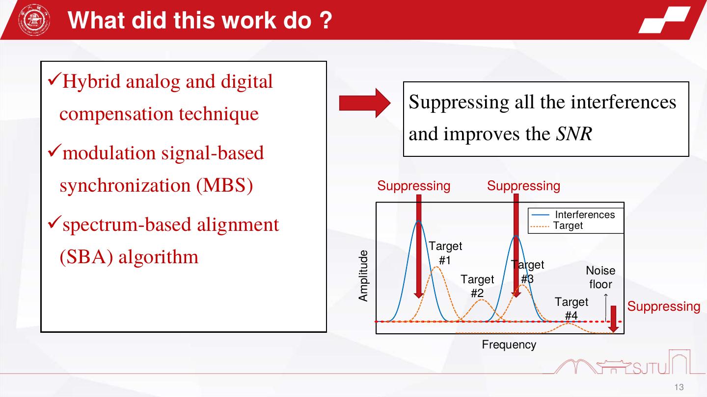
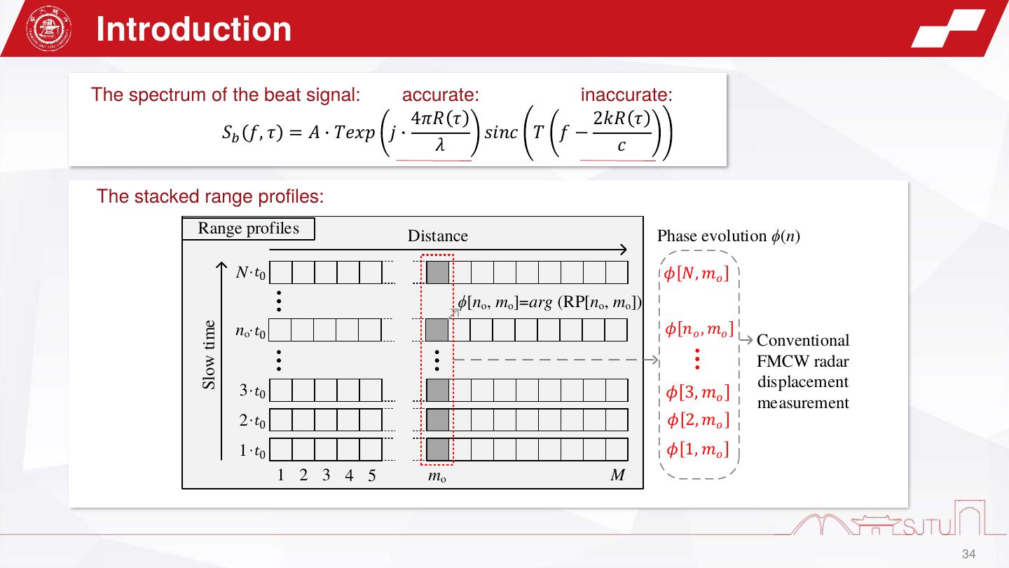
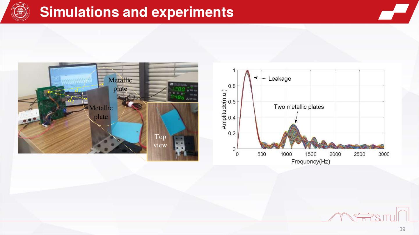
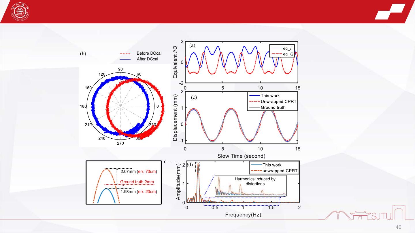
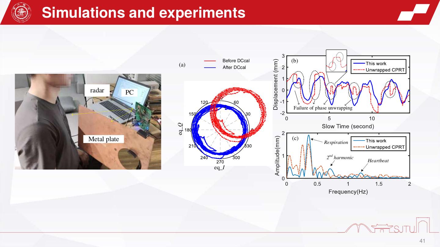
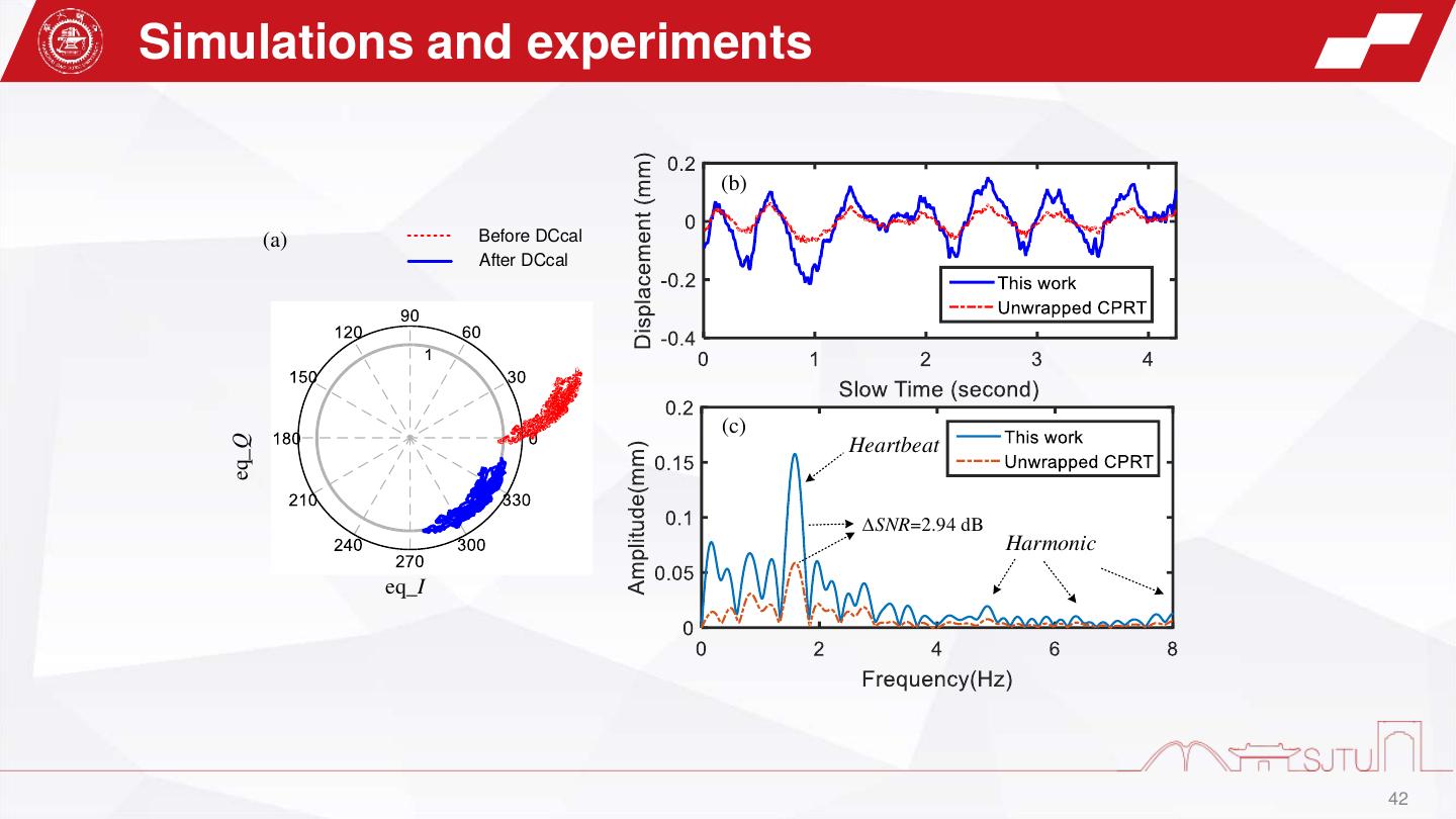
近年来,基于雷达的近距智能感知的得到广泛关注。主要应用领域有:手势交互、室内定位、呼吸心跳监测、血压监测等。与传统的长距军、民用雷达以及中距的车载雷达不同,近距雷达工作距离通常小于十米,探测环境也更为复杂,面临着严重的收发泄露和环境杂波干扰。针对这一干扰问题,我们提出了两种解决方案。第一种是模拟和数字混合补偿技术,通过预存的抗干扰信号在模拟域和数字域中对干扰进行两次补偿,实现对干扰的深度补偿。补偿过程中提出了一种新颖的基于调制信号的同步 (MBS) 技术,用于在补偿过程中将实时 IF 信号与抗干扰信号同步。通过显著抑制收发泄漏和环境杂波,该技术大大提高了中频信号的信干比(SIR),并使得检测具有弱反射的目标成为可能。此外,模拟补偿能够充分利用模数转换器 (ADC)的动态范围,这将减少量化噪声的影响,从而提高信噪比(SNR)。第二种是抗杂波的生命体征提取算法。用于稳定的生命体征探测。通过将调频连续波(FMCW)雷达的距离-时间图中目标列的实部虚部结合起来,组成了单频连续波(CW)雷达信号,再进一步利用CW雷达的圆拟合算法,去掉了环境杂波的影响。上面两项工作分别发表于TMTT,TbioCas期刊。
刘劲涛, 上海交通大学人工智能研究院博士生, ,指导老师是顾昌展副教授。主要研究兴趣集中于微波/毫米波电路和系统、近程雷达传感器和传感系统。目前以一作身份于TMTT, TbioCas, IEEE sensors journal, MWCL,IMS等会议或期刊发表论文9篇。
展开查看详情
1 .基于雷达的近距智能感知 汇报人: 刘劲涛 导师: 顾昌展 Monday, March 28, 2022
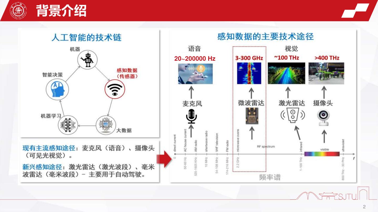
2 .背景介绍 20~200000 Hz 2
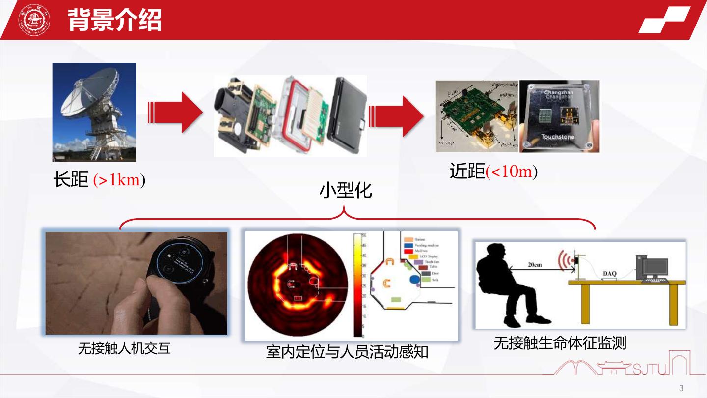
3 . 背景介绍 长距 (>1km) 近距(<10m) 小型化 无接触人机交互 无接触生命体征监测 室内定位与人员活动感知 3
4 . 案例1:手机雷达 雷达手势交互项目Soli 60GHz gesture radar , 2015 C. Gu, J. Lien, 2019 谷歌2019年最新Pixel4手机雷达模块设计 Soli Alpha DevKit, 2015 负责人 C. Gu, et al., IEEE Microwave Soli-enabled smartwatch, 2016 Magazine, 2019 4
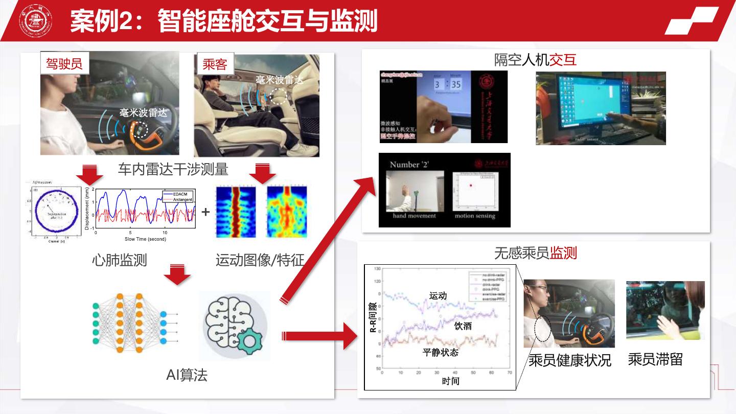
5 . 案例2:智能座舱交互与监测 驾驶员 乘客 隔空人机交互 毫米波雷达 毫米波雷达 车内雷达干涉测量 + 无感乘员监测 心肺监测 运动图像/特征 运动 R-R间隙 饮酒 平静状态 乘员健康状况 乘员滞留 AI算法 时间
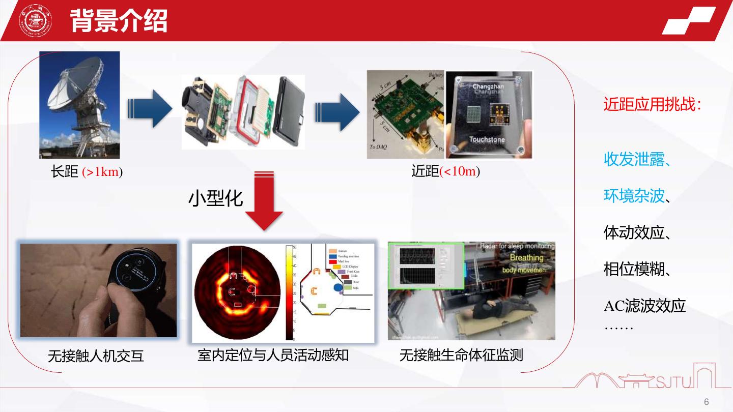
6 . 背景介绍 近距应用挑战: 收发泄露、 长距 (>1km) 近距(<10m) 小型化 环境杂波、 体动效应、 相位模糊、 AC滤波效应 …… 无接触人机交互 室内定位与人员活动感知 无接触生命体征监测 6
7 . Part1: Mitigation of Leakage and Stationary Clutters in Short- Range FMCW Radar With Hybrid Analog and Digital Compensation Technique By Jingtao Liu Supervisor: Changzhan Gu Monday, March 28, 2022
8 . 1 Introduction Part1 2 Theory 目 录 Contents 3 Experiments 4 Conclusion
9 . 1 Introduction Part1 2 Theory 目 录 Contents 3 Experiments 4 Conclusion
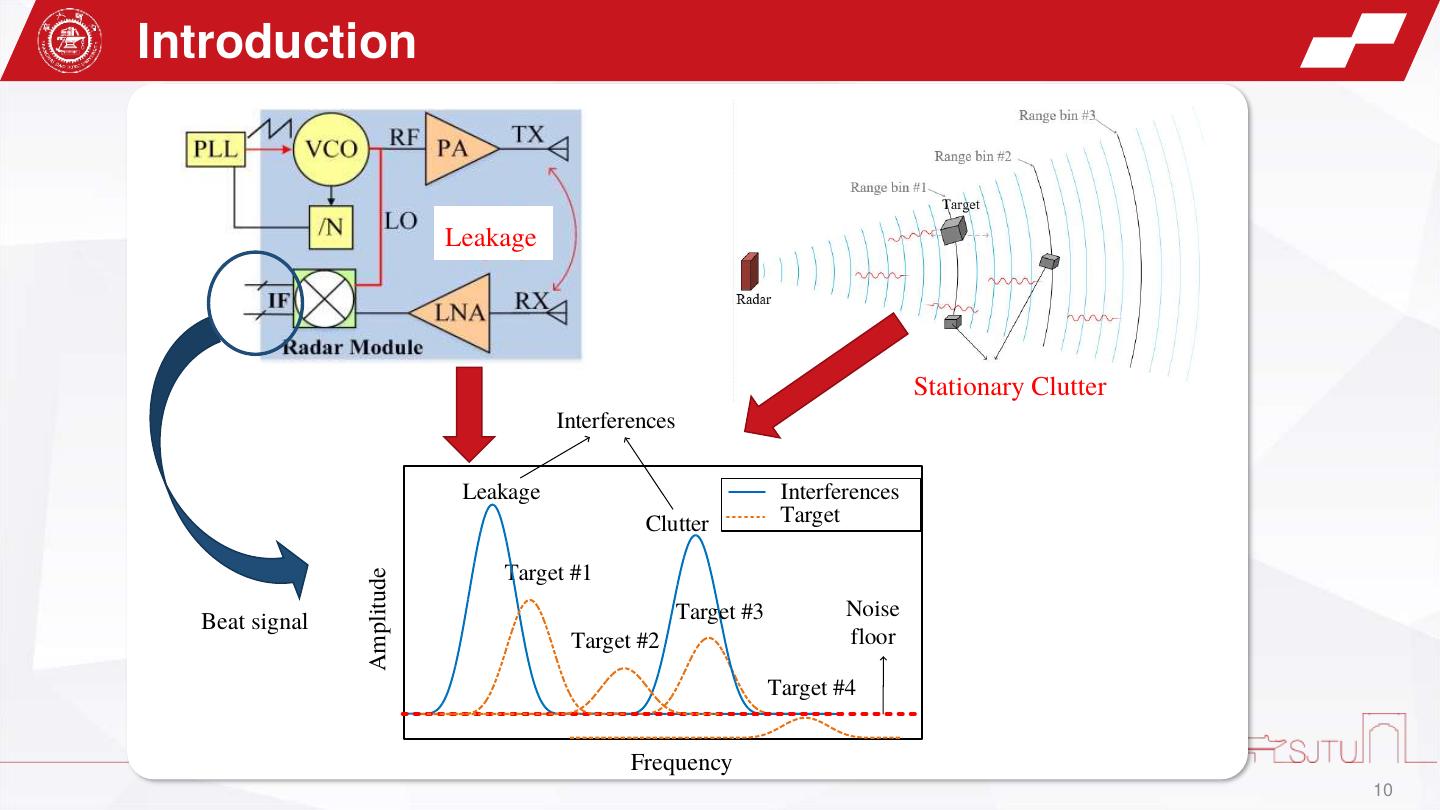
10 .Introduction Leakage Stationary Clutter Stationary Clutter Interferences Leakage Interferences Clutter Target Target #1 Amplitude Target #3 Noise Beat signal Target #2 floor Target #4 Frequency 10
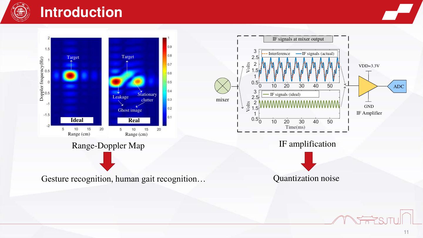
11 . Introduction IF signals at mixer output 3 Interference IF signals (actual) Target Target 2.5 Doppler frequency(Hz) 2 Volts VDD=3.3V 1.5 1 0.5 0 10 20 30 40 50 ADC Stationary 3 IF signals (ideal) Leakage clutter mixer 2.5 2 Volts 1.5 GND Ghost image 1 IF Amplifier Ideal Real 0.5 0 10 20 30 40 50 Time(ms) Range (cm) Range (cm) Range-Doppler Map IF amplification Gesture recognition, human gait recognition… Quantization noise 11
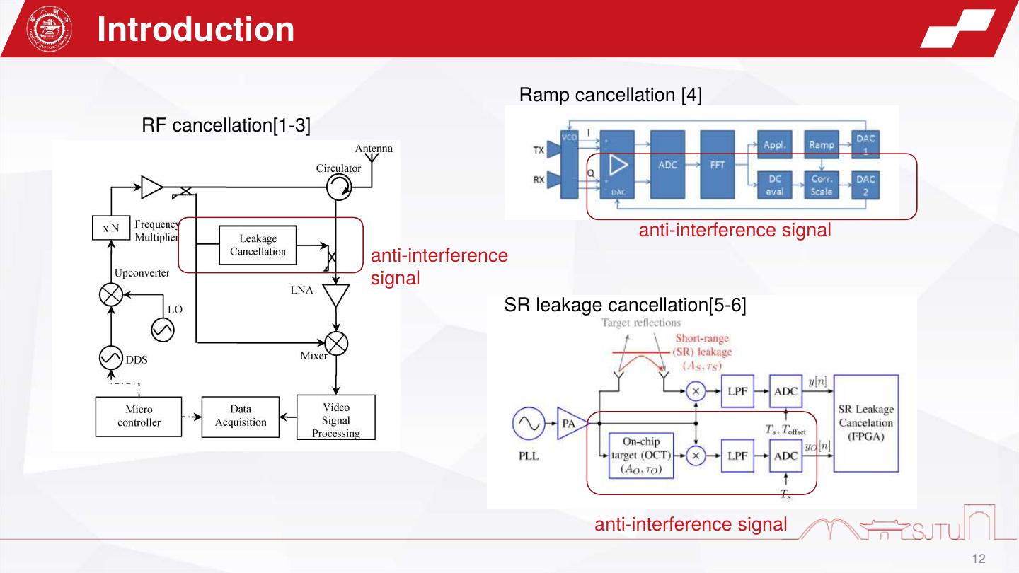
12 .Introduction Ramp cancellation [4] RF cancellation[1-3] anti-interference signal anti-interference signal SR leakage cancellation[5-6] anti-interference signal 12
13 . What did this work do ? ✓Hybrid analog and digital Suppressing all the interferences compensation technique and improves the SNR ✓modulation signal-based synchronization (MBS) Suppressing Suppressing Interferences ✓spectrum-based alignment Target Target (SBA) algorithm Amplitude #1 Target Noise Target #3 floor #2 Target Suppressing #4 Frequency 13
14 . 1 Introduction Part1 2 Theory 目 录 Contents 3 Experiments 4 Conclusion
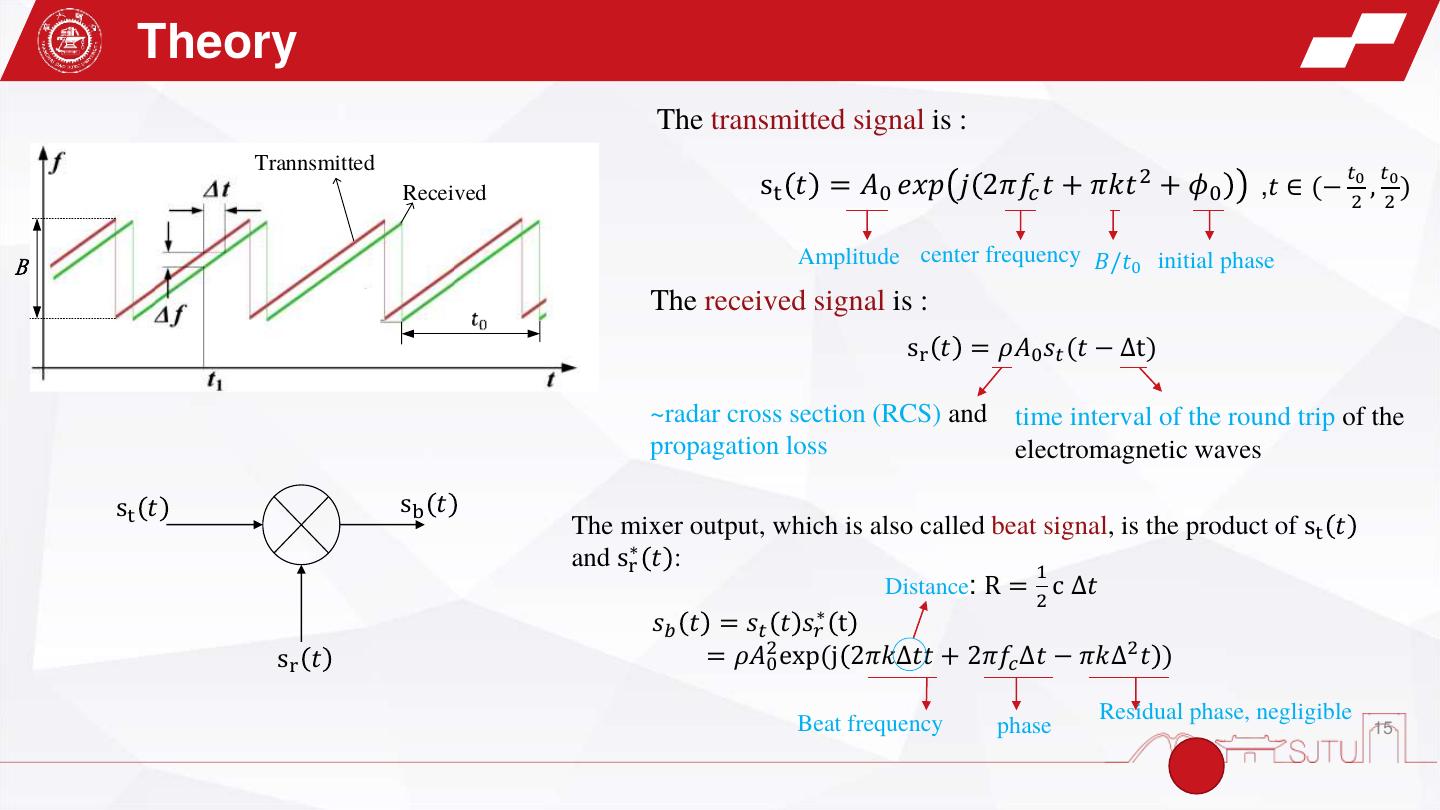
15 . Theory The transmitted signal is : Trannsmitted 𝑡0 𝑡0 Received st 𝑡 = 𝐴0 𝑒𝑥𝑝 𝑗 2𝜋𝑓𝑐 𝑡 + 𝜋𝑘𝑡 2 + 𝜙0 ,𝑡 ∈ (− , ) 2 2 B Amplitude center frequency 𝐵/𝑡0 initial phase The received signal is : sr 𝑡 = 𝜌𝐴0 𝑠𝑡 (𝑡 − Δt) ~radar cross section (RCS) and time interval of the round trip of the propagation loss electromagnetic waves st 𝑡 sb 𝑡 The mixer output, which is also called beat signal, is the product of st 𝑡 and sr∗ 𝑡 : 1 Distance: R = c ∆𝑡 2 ∗ 𝑠𝑏 𝑡 = 𝑠𝑡 𝑡 𝑠𝑟 t sr 𝑡 = 𝜌𝐴20 exp(j 2𝜋𝑘∆𝑡𝑡 + 2𝜋𝑓𝑐 ∆𝑡 − 𝜋𝑘∆2 𝑡 ) Beat frequency Residual phase, negligible phase 15
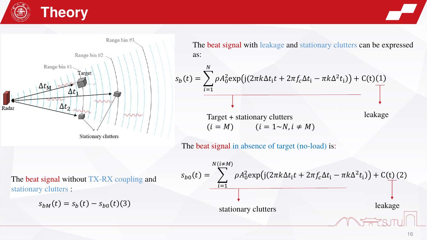
16 . Theory The beat signal with leakage and stationary clutters can be expressed as: 𝑁 𝑠𝑏 𝑡 = 𝜌𝐴20 exp j 2𝜋𝑘∆𝑡i 𝑡 + 2𝜋𝑓𝑐 ∆𝑡i − 𝜋𝑘∆2 𝑡i +C t 1 ∆𝑡M 𝑖=1 ∆𝑡1 ∆𝑡2 Target + stationary clutters leakage (𝑖 = 𝑀) (𝑖 = 1~𝑁, 𝑖 ≠ 𝑀) The beat signal in absence of target (no-load) is: 𝑁(𝑖≠𝑀) 𝑠𝑏0 𝑡 = 𝜌𝐴20 exp j 2𝜋𝑘∆𝑡i 𝑡 + 2𝜋𝑓𝑐 ∆𝑡i − 𝜋𝑘∆2 𝑡i + C t (2) The beat signal without TX-RX coupling and 𝑖=1 stationary clutters : 𝑠𝑏𝑀 𝑡 = 𝑠𝑏 𝑡 − 𝑠𝑏0 𝑡 3 leakage stationary clutters 16
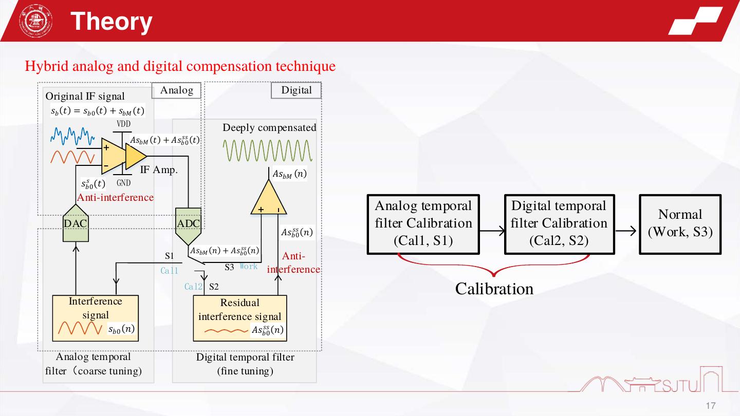
17 . Theory Hybrid analog and digital compensation technique Analog Digital Original IF signal 𝑠𝑏 (𝑡) = 𝑠𝑏0 (𝑡) + 𝑠𝑏𝑀 (𝑡) VDD Deeply compensated 𝑠𝑠 ( ) + 𝐴𝑠𝑏𝑀 (𝑡) + 𝐴𝑠𝑏0 𝑡 - IF Amp. 𝐴𝑠𝑏𝑀 (𝑛) 𝑠 GND 𝑠𝑏0 (𝑡) Anti-interference Analog temporal Digital temporal + - Normal DAC ADC 𝑠𝑠 ( ) filter Calibration filter Calibration 𝐴𝑠𝑏0 𝑛 (Work, S3) 𝑠𝑠 ( ) (Cal1, S1) (Cal2, S2) 𝐴𝑠𝑏𝑀 (𝑛) + 𝐴𝑠𝑏0 𝑛 S1 Anti- Cal1 S3 Work interference Cal2 S2 Calibration Interference Residual signal interference signal 𝑠𝑏0 (𝑛) 𝑠𝑠 ( ) 𝐴𝑠𝑏0 𝑛 Analog temporal Digital temporal filter filter(coarse tuning) (fine tuning) 17
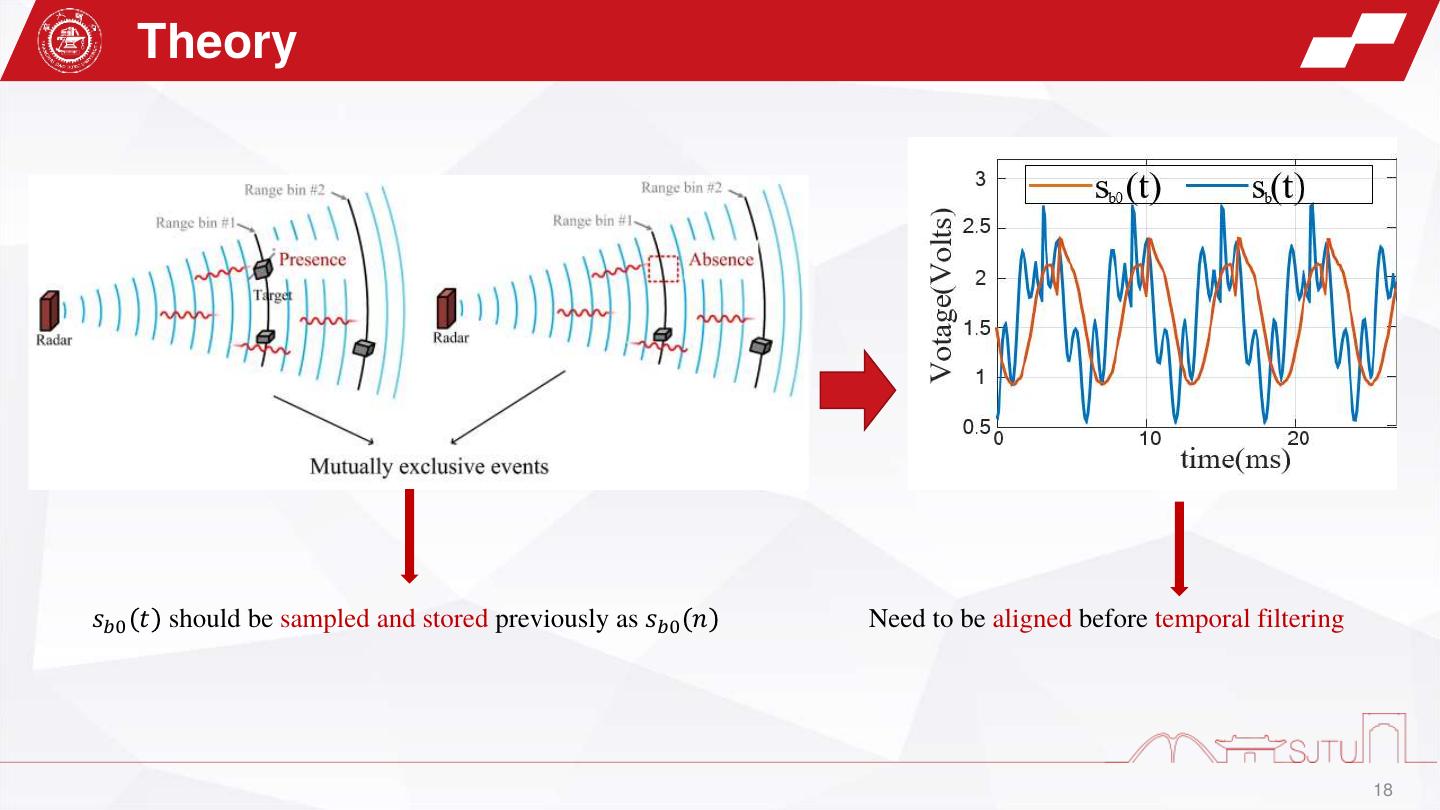
18 . Theory 𝑠𝑏0 𝑡 should be sampled and stored previously as 𝑠𝑏0 𝑛 Need to be aligned before temporal filtering 18
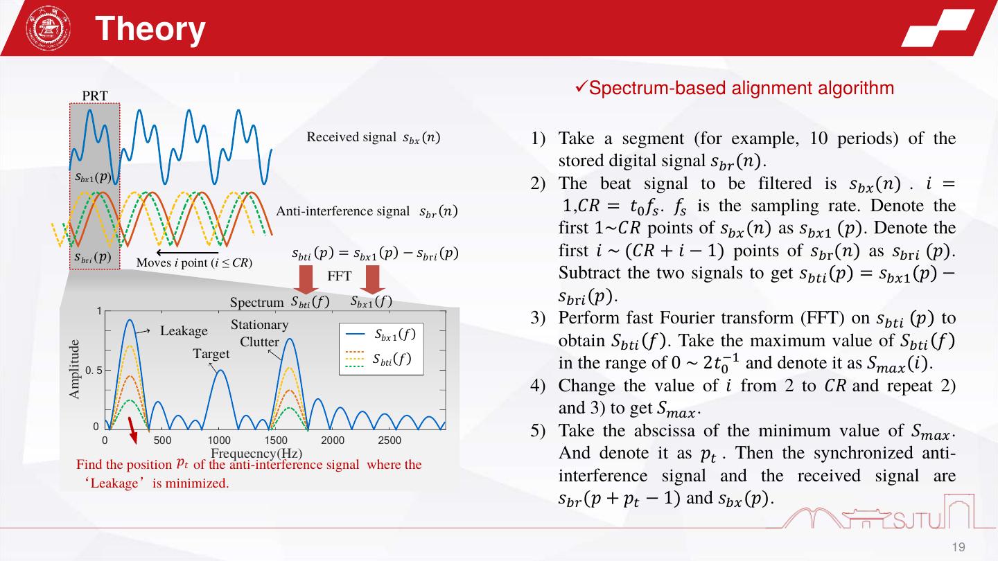
19 . Theory PRT ✓Spectrum-based alignment algorithm Received signal 𝑠𝑏𝑥 (𝑛) 1) Take a segment (for example, 10 periods) of the stored digital signal 𝑠𝑏𝑟 (𝑛). ( ) 1 2) The beat signal to be filtered is 𝑠𝑏𝑥 (𝑛) . 𝑖 = Anti-interference signal 𝑠𝑏𝑟 (𝑛) 1,𝐶𝑅 = 𝑡0 𝑓𝑠 . 𝑓𝑠 is the sampling rate. Denote the first 1~𝐶𝑅 points of 𝑠𝑏𝑥 (𝑛) as 𝑠𝑏𝑥1 (𝑝). Denote the ri ( ) 𝑠𝑏𝑡𝑖 (𝑝) = 𝑠𝑏𝑥 1 (𝑝) − 𝑠𝑏r𝑖 (𝑝) first 𝑖 ~ (𝐶𝑅 + 𝑖 − 1) points of 𝑠𝑏r (𝑛) as 𝑠𝑏r𝑖 (𝑝). Moves i point (i CR) FFT Subtract the two signals to get 𝑠𝑏𝑡𝑖 𝑝 = 𝑠𝑏𝑥1 𝑝 − Spectrum 𝑆𝑏𝑡𝑖 (𝑓) 𝑆𝑏𝑥 1 (𝑓) 𝑠𝑏r𝑖 (𝑝). 1 Stationary 3) Perform fast Fourier transform (FFT) on 𝑠𝑏𝑡𝑖 𝑝 to Leakage 𝑆𝑏𝑥 1 (𝑓) Clutter obtain 𝑆𝑏𝑡𝑖 𝑓 . Take the maximum value of 𝑆𝑏𝑡𝑖 𝑓 Amplitude Target 0.5 𝑆𝑏𝑡𝑖 (𝑓) in the range of 0 ~ 2𝑡0−1 and denote it as 𝑆𝑚𝑎𝑥 (𝑖). 4) Change the value of 𝑖 from 2 to 𝐶𝑅 and repeat 2) and 3) to get 𝑆𝑚𝑎𝑥 . 0 0 500 1000 1500 2000 2500 5) Take the abscissa of the minimum value of 𝑆𝑚𝑎𝑥 . Frequecncy(Hz) And denote it as 𝑝𝑡 . Then the synchronized anti- Find the position 𝑝𝑡 of the anti-interference signal where the Leakage is minimized. interference signal and the received signal are 𝑠𝑏𝑟 (𝑝 + 𝑝𝑡 − 1) and 𝑠𝑏𝑥 (𝑝). 19
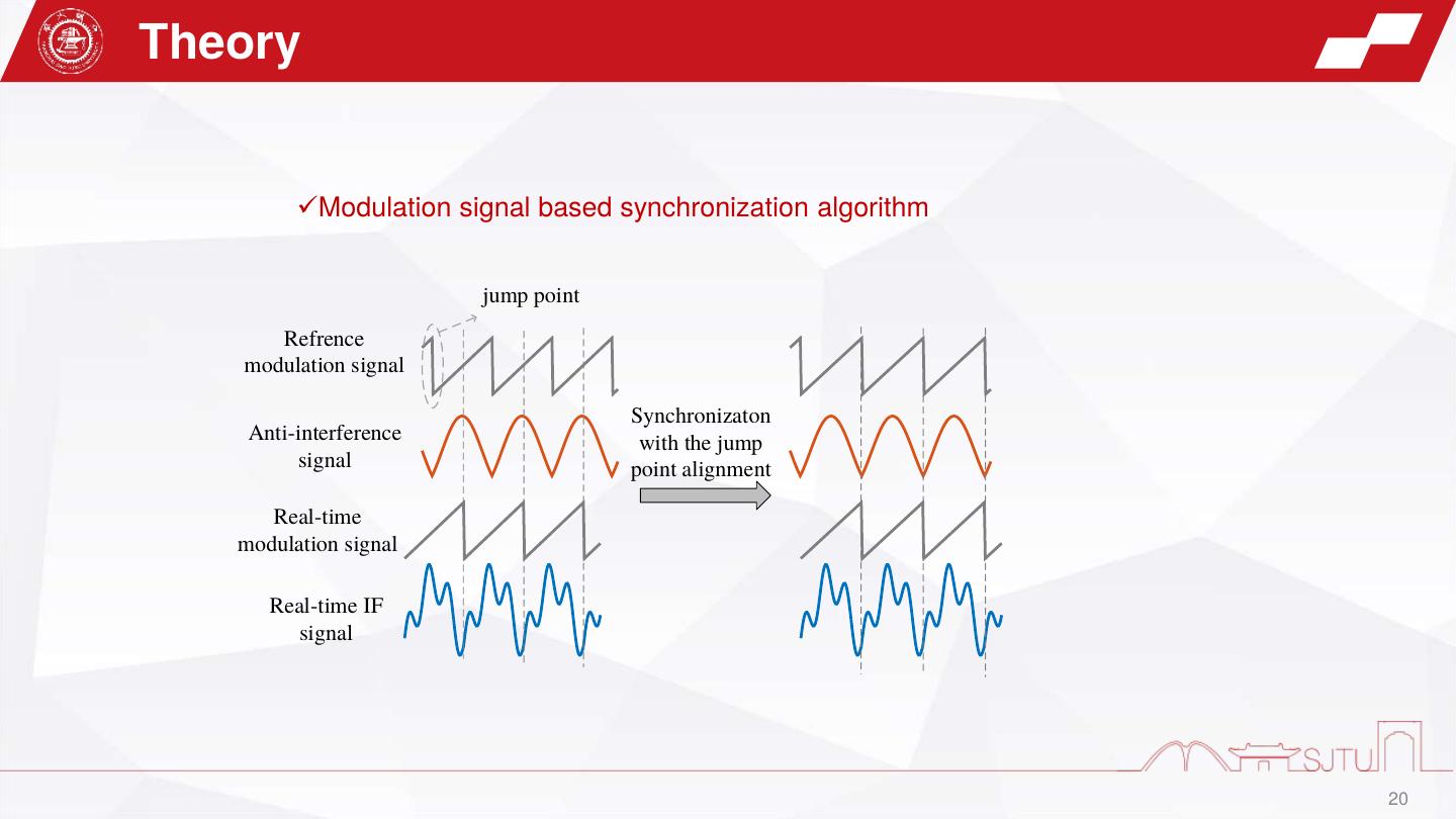
20 .Theory ✓Modulation signal based synchronization algorithm jump point Refrence modulation signal Synchronizaton Anti-interference with the jump signal point alignment Real-time modulation signal Real-time IF signal 20
21 . 1 Introduction Part1 2 Theory 目 录 Contents 3 Experiments 4 Conclusion
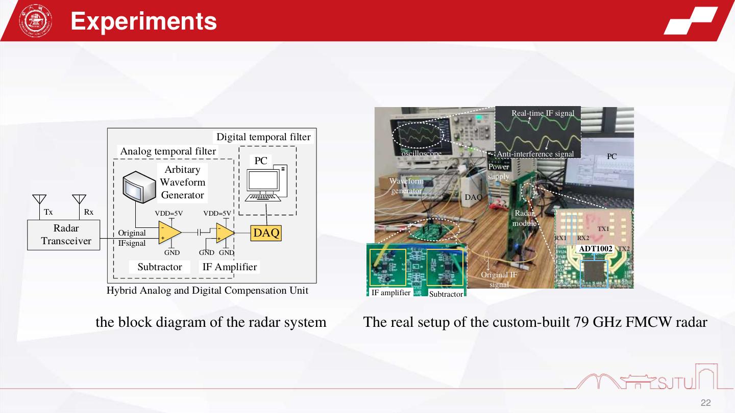
22 . Experiments z Real-time IF signal Digital temporal filter Analog temporal filter oscilloscope Anti-interference signal PC PC Power Arbitary supply Waveform Waveform generator Generator DAQ Tx Rx VDD=5V VDD=5V Radar module Radar - - TX1 Original + + DAQ RX1 RX2 Transceiver IFsignal GND GND GND ADT1002 TX2 Subtractor IF Amplifier Original IF signal Hybrid Analog and Digital Compensation Unit IF amplifier Subtractor the block diagram of the radar system The real setup of the custom-built 79 GHz FMCW radar 22
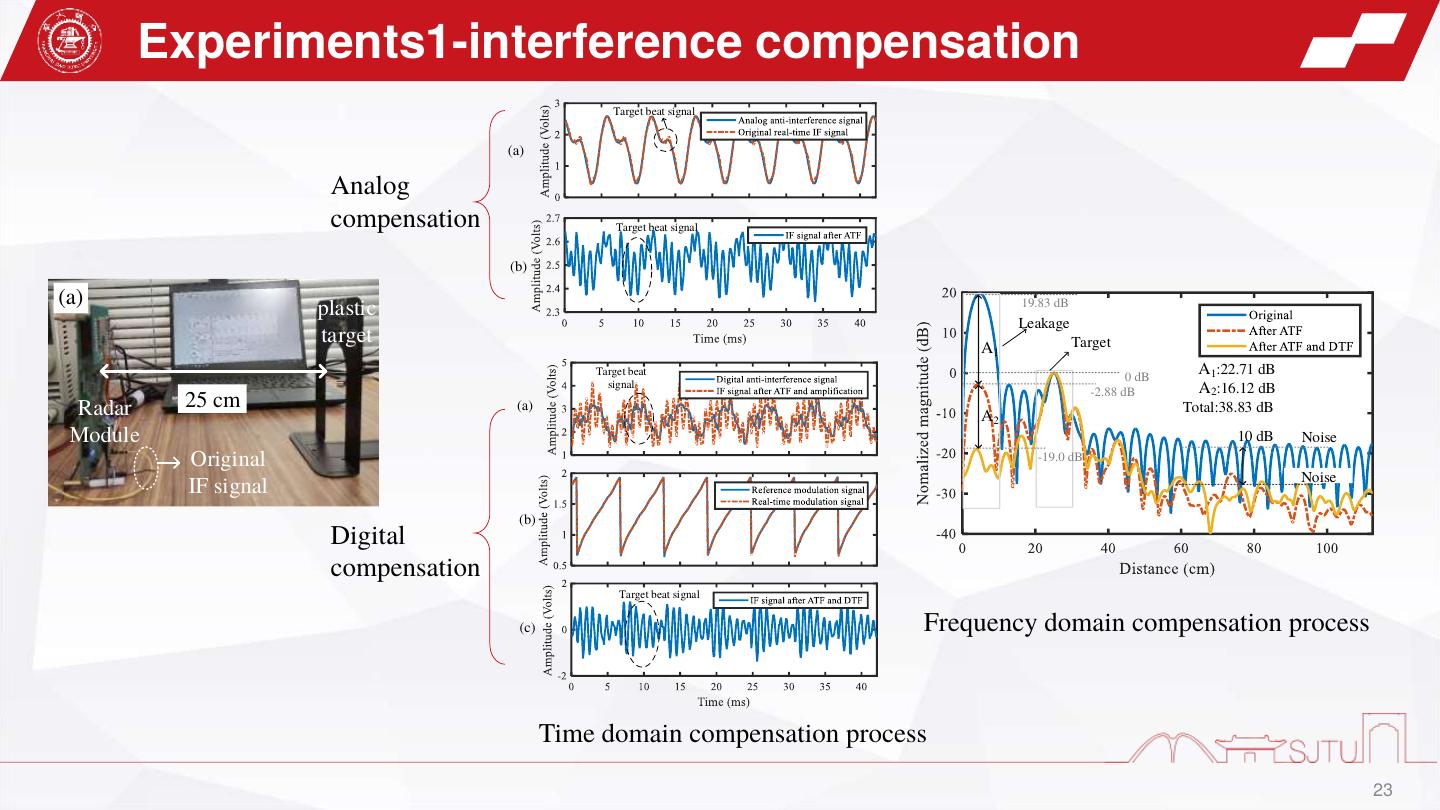
23 . Experiments1-interference compensation Target beat signal (a) Analog compensation Target beat signal (b) (a) plastic 19.83 dB Leakage target Target A1 Target beat 0 dB A1:22.71 dB signal A2:16.12 dB -2.88 dB Radar 25 cm (a) Total:38.83 dB A2 Module 10 dB Noise Original -19.0 dB Noise IF signal (b) Digital compensation Target beat signal (c) Frequency domain compensation process Time domain compensation process 23
24 . Experiments2-Weak target detection (a) Analog compensation (b) (b) Leakage Target 18 cm 0 dB -5.8 dB Radar crabstick -7.6 dB Target beat Module signal Original (a) IF signal (b) Digital compensation (c) Frequency domain compensation process Target beat signal Time domain compensation process 24
25 .Experiments3-gesture sensing Leakage Stationary clutter Stationary A1 Target A1:21.9 dB A3:16.8 dB clutter A2:14.6 dB A4:7.2 dB 0 dB Total:35.5 dB Total:24.0 dB A3 15 cm Moving A2 A4 5dB Noise Radar 28 cm Noise Module Original IF signal Frequency domain compensation process Part2 Leakage (a) (b) Stationary Palm Palm clutter Part1 Ghost images induced by the interferences Palm trajectory Range Doppler map 25
26 . 1 Introduction Part1 2 Theory 目 录 Contents 3 Experiments 4 Conclusion
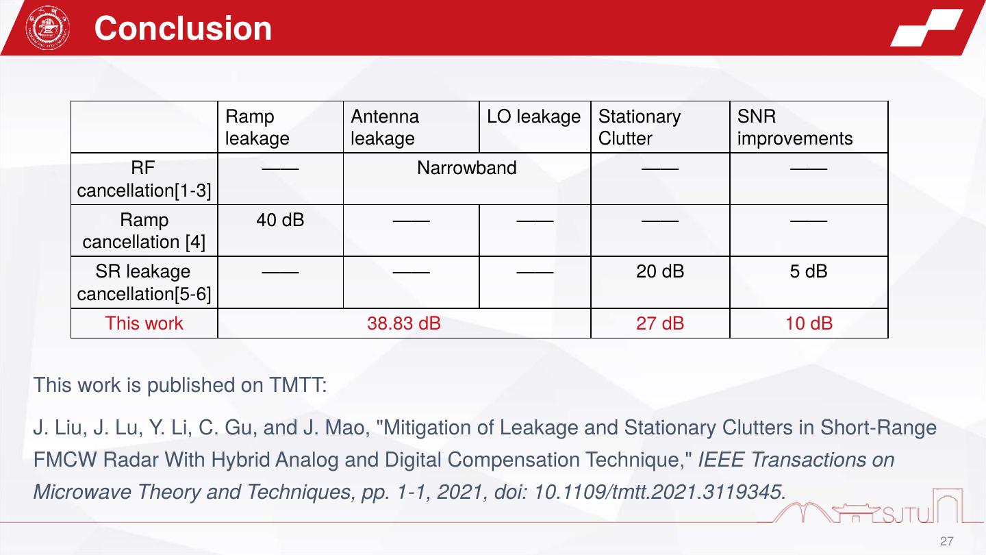
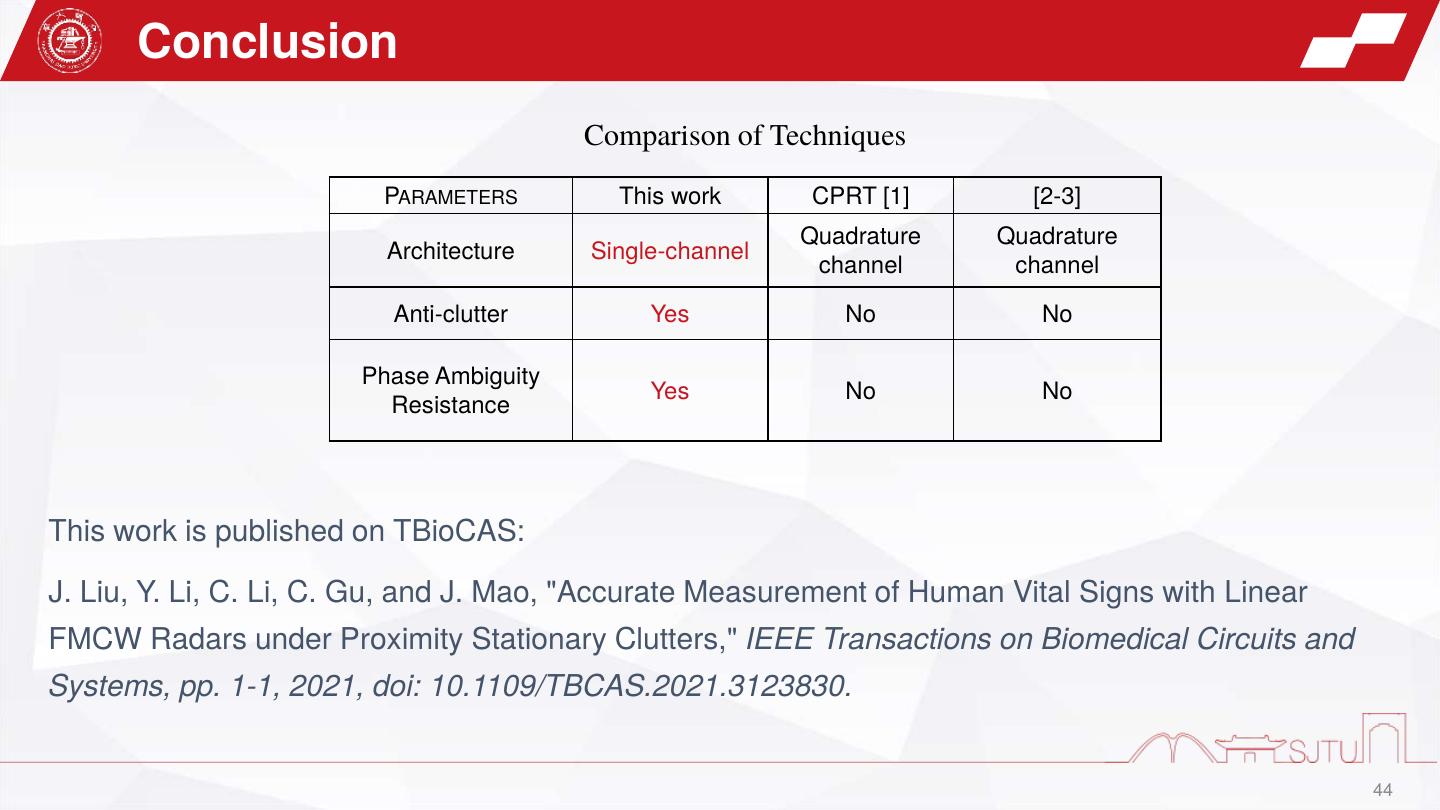
27 . Conclusion Ramp Antenna LO leakage Stationary SNR leakage leakage Clutter improvements RF —— Narrowband —— —— cancellation[1-3] Ramp 40 dB —— —— —— —— cancellation [4] SR leakage —— —— —— 20 dB 5 dB cancellation[5-6] This work 38.83 dB 27 dB 10 dB This work is published on TMTT: J. Liu, J. Lu, Y. Li, C. Gu, and J. Mao, "Mitigation of Leakage and Stationary Clutters in Short-Range FMCW Radar With Hybrid Analog and Digital Compensation Technique," IEEE Transactions on Microwave Theory and Techniques, pp. 1-1, 2021, doi: 10.1109/tmtt.2021.3119345. 27
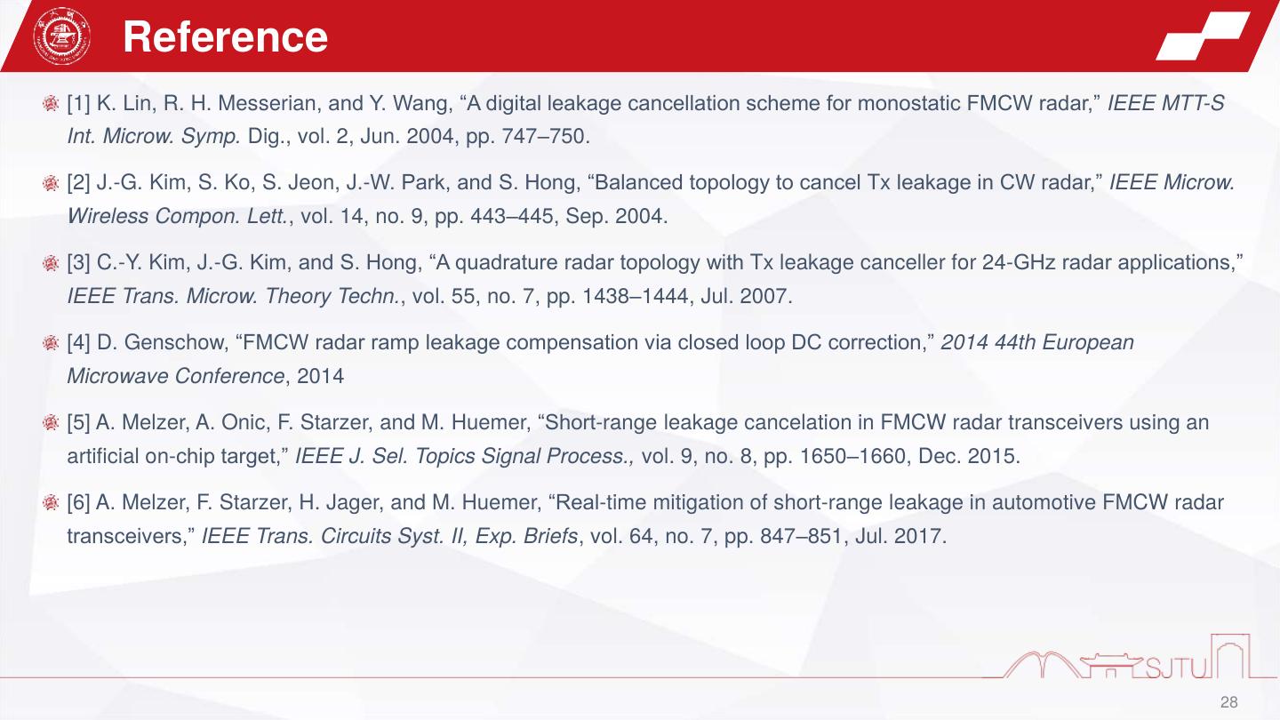
28 . Reference [1] K. Lin, R. H. Messerian, and Y. Wang, “A digital leakage cancellation scheme for monostatic FMCW radar,” IEEE MTT-S Int. Microw. Symp. Dig., vol. 2, Jun. 2004, pp. 747–750. [2] J.-G. Kim, S. Ko, S. Jeon, J.-W. Park, and S. Hong, “Balanced topology to cancel Tx leakage in CW radar,” IEEE Microw. Wireless Compon. Lett., vol. 14, no. 9, pp. 443–445, Sep. 2004. [3] C.-Y. Kim, J.-G. Kim, and S. Hong, “A quadrature radar topology with Tx leakage canceller for 24-GHz radar applications,” IEEE Trans. Microw. Theory Techn., vol. 55, no. 7, pp. 1438–1444, Jul. 2007. [4] D. Genschow, “FMCW radar ramp leakage compensation via closed loop DC correction,” 2014 44th European Microwave Conference, 2014 [5] A. Melzer, A. Onic, F. Starzer, and M. Huemer, “Short-range leakage cancelation in FMCW radar transceivers using an artificial on-chip target,” IEEE J. Sel. Topics Signal Process., vol. 9, no. 8, pp. 1650–1660, Dec. 2015. [6] A. Melzer, F. Starzer, H. Jager, and M. Huemer, “Real-time mitigation of short-range leakage in automotive FMCW radar transceivers,” IEEE Trans. Circuits Syst. II, Exp. Briefs, vol. 64, no. 7, pp. 847–851, Jul. 2017. 28
29 . Part2: Accurate Measurement of Human Vital Signs with Linear FMCW Radars under Proximity Stationary Clutters By Jingtao Liu Supervisor: Changzhan Gu Monday, March 28, 2022


